Review the part design
Discuss wall thickness transitions, draft angles, undercuts and assembly features that may affect filling, sink marks or part release.

Tooling for electronic, instrument and industrial equipment components starts with an agreed part design and ends with a defined acceptance and delivery scope. We discuss draft angles, wall thickness and demolding early so the tool design follows the part's real requirements.
A custom injection mold starts with the part function, expected quantity and the press or production plan. Early drawing review can identify changes before the tooling design is finalized.
Discuss wall thickness transitions, draft angles, undercuts and assembly features that may affect filling, sink marks or part release.
Confirm the resin grade, expected volume, cavity plan, mold interfaces and any customer-specified components before quoting.
Agree sample quantities, inspection requirements, acceptance criteria and whether the mold will be shipped or used for molding production.
Design for Manufacturing (DFM) connects the part designer and mold team before tooling. We discuss uneven walls, sink marks, incomplete filling, draft angles and release, then agree any proposed changes with the customer. The scope and timing of the review depend on the project.
Evaluate draw directions, side shut-offs, and deep rib draft angles. Proper draft prevents drag marks on cosmetic faces and guarantees smooth automated part ejection.
Verify uniform nominal walls (1.5 to 3.0 mm) and maintain rib-to-wall ratios under 60% to eliminate surface sink marks, internal voids, and differential thermal warpage.
Every recommended 3D modification is documented with CAD cross-sections and sent to the client for engineering sign-off before manufacturing drawings are finalized.
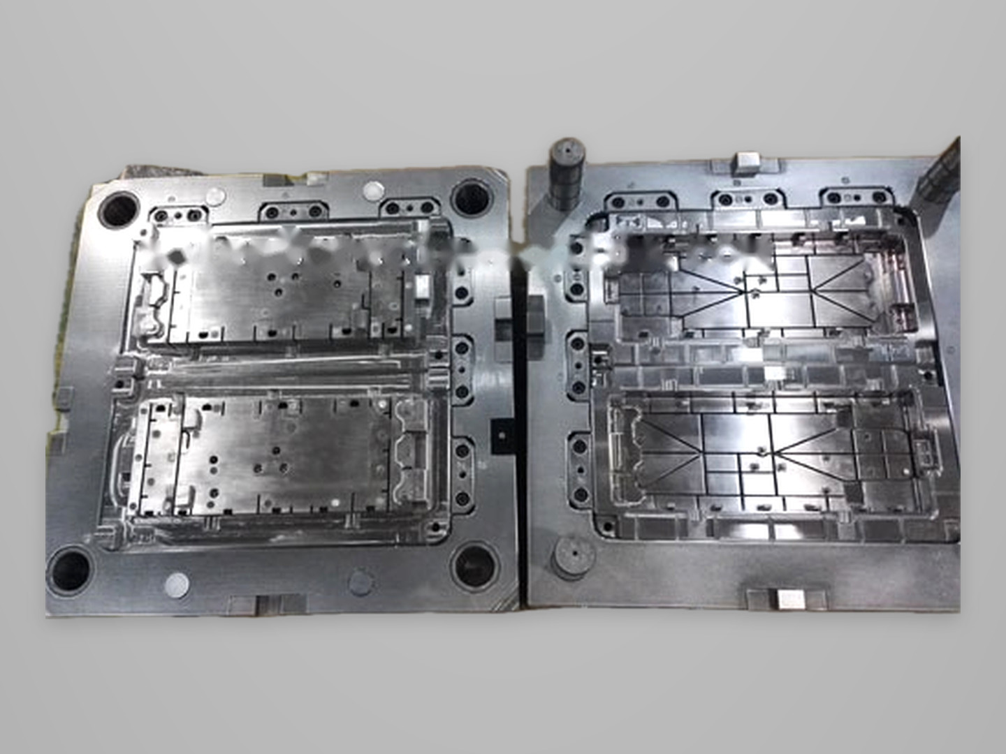
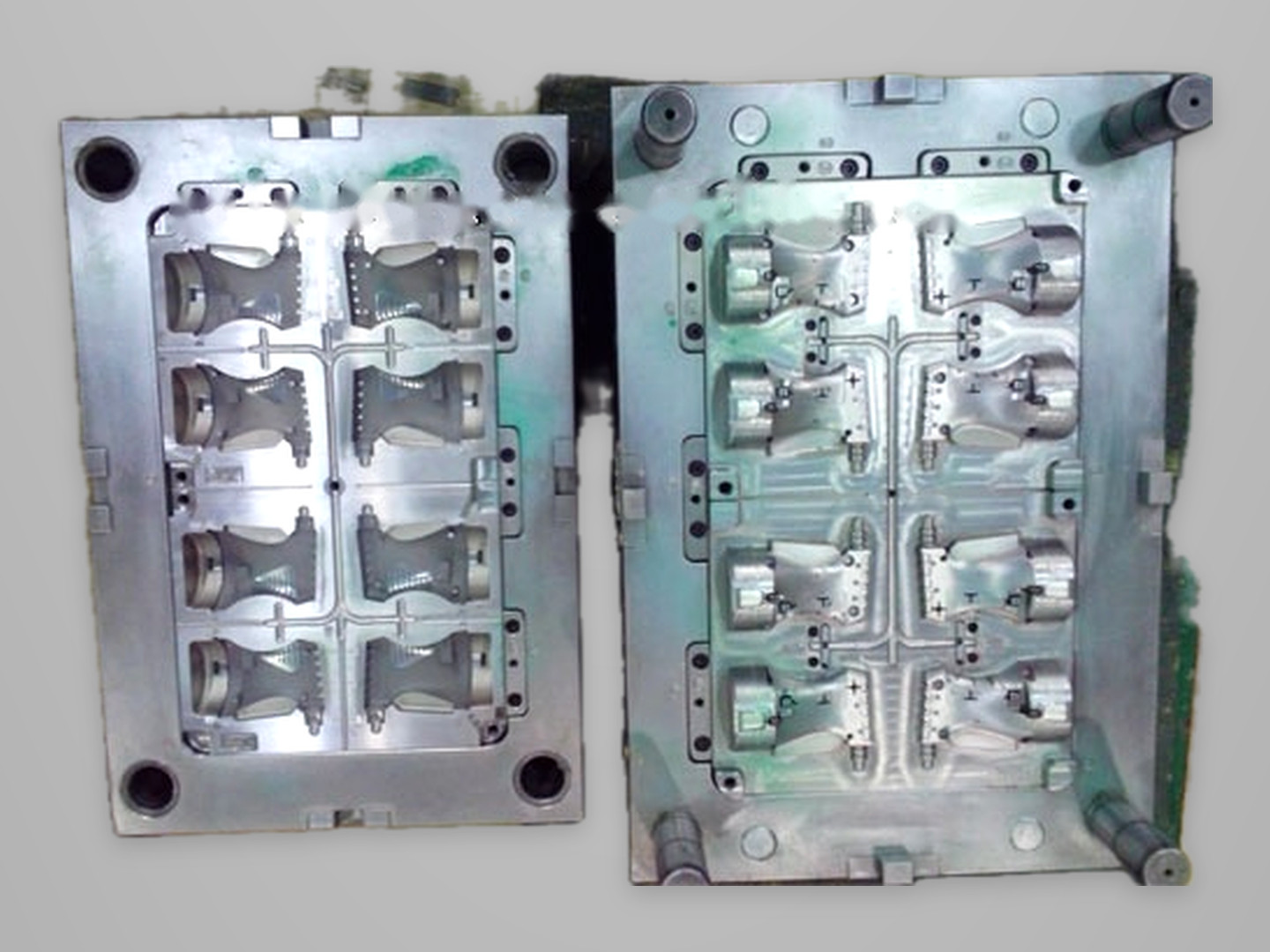
CNC milling operations and the EDM spark erosion workshop for precision mold manufacturing.


SPI mold classification establishes standard tooling specifications based on lifetime cycle volume, mold base hardness, and core/cavity steel grades. Class 101 tools utilize through-hardened steels (48 to 54 HRC) rated for over 1,000,000 cycles, whereas Class 104 tools utilize pre-hardened P20 steel for pilot production under 100,000 cycles.
Selecting the appropriate SPI tooling class matches your production volume to tooling investment. Nodinson engineers custom mold making and electronic enclosure tooling strictly adhering to North American SPI standards and European DIN standards, featuring genuine European tool steels (Böhler, Uddeholm, Kind & Co) accompanied by verified Mill Test Certificates (MTC).
| SPI Tooling Class | Rated Tool Life | Core & Cavity Steel | Mold Base Specification | Construction Features | Typical Production Applications |
|---|---|---|---|---|---|
| Class 101 Molds | 1,000,000+ cycles | Hardened tool steel (48 to 54 HRC, e.g., DIN 1.2343 ESR, AISI H13) | Minimum 280 BHN (DIN 1.2311 or DME #2 / #3 steel) | Guided ejection, wear plates on slides, hardened slides, cooling line plating | Extremely high-volume automotive connectors, consumer electronics, caps |
| Class 102 Molds | Up to 1,000,000 cycles | Tool steel hardened to 48 HRC minimum (DIN 1.2344, 1.2083 Stavax) | Minimum 280 BHN (DIN 1.2312 or DME #2 steel) | Guided ejection, hardened slide wear plates, corrosion-resistant water circuits | High-volume consumer appliances, industrial meters, medical enclosures |
| Class 103 Molds | Up to 500,000 cycles | Pre-hardened tool steel (28 to 36 HRC, DIN 1.2738, 1.2311, P20) | Standard carbon steel (DIN 1.1730 or DME #1 steel) | Standard ejector guides, conventional cooling channels, standard bushings | Medium-volume production, electronic instrument housings, commercial parts |
| Class 104 Molds | Up to 100,000 cycles | Pre-hardened steel or aluminum (DIN 1.2311, P20, or QC-10 aluminum) | Standard carbon steel or aluminum base | Simplified ejection, non-hardened guide pins, standard water lines | Pilot runs, bridge tooling, niche instrumentation, market validation |
Nine views of mold-making work areas and tooling.


Precision mold manufacturing progresses through ten disciplined milestones from non-disclosure agreement and 2D/3D CAD review through CNC milling, vacuum heat treatment, EDM spark erosion, T1 sampling, and CMM inspection. Every export tool completes an 18-point pre-shipment checklist with certified steel Mill Test Certificates.
Set the NDA parties, technical scope and encrypted exchange method before transmitting proprietary 2D/3D CAD models.
Customer checkpoint: Confirm the NDA terms and authorized project file repositories.Use drawing revisions, target resin, annual volume, and required surface textures to establish a precise quotation scope.
Customer checkpoint: Confirm CAD revisions, critical-to-function dimensions, and commercial terms.Align engineering schedules, milestone dates, payment terms, and technical specifications before cutting steel.
Customer checkpoint: Approve the commercial contract and engineering project schedule.Review wall thickness, filling, draft angles, release and tooling considerations with the part designer.
Customer checkpoint: Review recommendations and approve part design changes before finalizing tooling.Execute rheological moldflow simulation for high-risk geometries to predict weld line locations, fiber orientation, and cooling efficiency.
Customer checkpoint: Confirm simulation parameters and agree on runner/gate sizing.Complete detailed 3D mold assembly designs including cooling circuits, ejection layout, slide mechanisms, and press platen interfaces.
Customer checkpoint: Sign off on full 2D/3D mold drawings, DME/HASCO component specs, and BOM.Perform rough milling, stress-relief vacuum heat treatment to 48 to 52 HRC, finish CNC milling, Sodick wire EDM, and mirror polishing.
Customer checkpoint: Receive weekly photographic progress reports and CMM electrode logs.Mount mold in Haitian production press, qualify stable molding window, produce initial T1 samples, and perform full dimensional CMM metrology.
Customer checkpoint: Review T1 visual samples, FAI measurement reports, and process logs.Perform minor cavity adjustments, polish to specified SPI finish, or apply Mold-Tech chemical etching after dimensional approval.
Customer checkpoint: Approve golden samples (T2) and surface finish texture plaque.Execute 18-point pre-shipment mold checklist (cooling pressure test, slide interlocks, limit switches), pack certified steel MTCs, and crate.
Customer checkpoint: Approve final FAT verification report, packaging, and shipping documents.For turnkey export tooling, T1/T2 sample approval leads to mold factory acceptance testing (FAT), 18-point pre-shipment inspection, anti-rust preservation, and export crating. For domestic production, the approved tool transitions directly into qualified volume molding with FAI sign-off.
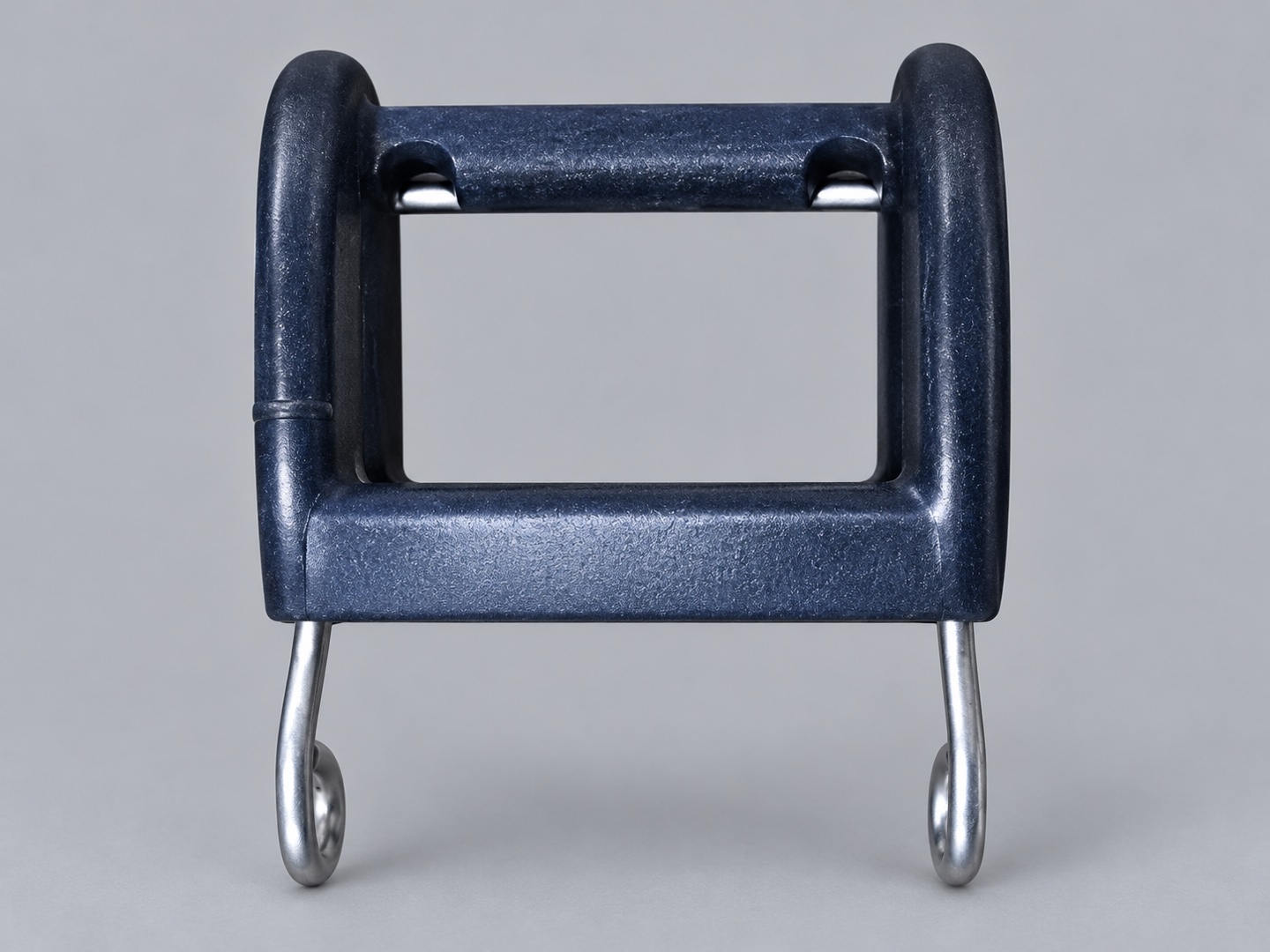
Explore related catalog parts. Images illustrate part types; confirm materials, dimensions and acceptance requirements for your project.
Moldflow is highly recommended for complex, thin-walled, or high-cosmetic parts where weld line positioning, air traps, and differential cooling warpage present tooling risks. For simple geometric parts, experienced DFM review is often sufficient.
For abrasive resins like PA66-GF30 or PBT-GF30, we specify high-wear tool steels through-hardened to 52 to 56 HRC, such as DIN 1.2379 (AISI D2), DIN 1.2343 ESR (H13), or Uddeholm Elmax powder metallurgy steel to ensure long-term dimensional retention.
We design export molds directly to DME (imperial) or HASCO (metric) component standards based on client press platen drawings, including exact locating ring diameters, sprue bushing radii, ejector tie-in patterns, and water coupler standards.
All proprietary 3D files are protected under legally binding non-disclosure agreements (NDAs) prior to data transfer. CAD data is processed on isolated, encrypted internal servers and never shared publicly.
Share the application, drawing revision, material requirements, expected quantity and acceptance needs. Sensitive files can be exchanged after an NDA through a channel we agree together.
Request a Quote