Insert supply and orientation
Share insert drawings, samples, plating requirements and who will supply the components. Review how the insert will be positioned during molding.

Metal inserts can be captured in molded plastic components for electrical, fastening or mechanical interfaces. For electronic and industrial equipment parts, insert geometry, supply condition, placement and inspection must be defined before tooling is approved.
Insert molding combines metal features and molded plastic in one component. Define the insert supply and how the finished part must assemble and perform before the tooling plan is agreed.
Share insert drawings, samples, plating requirements and who will supply the components. Review how the insert will be positioned during molding.
Identify threaded, electrical or mechanical interfaces and agree which dimensions and retention tests matter for the application.
Discuss insert handling and placement, labor involved, target quantity and inspection. The tooling and loading method depend on the part and agreed production scope.
Insert molding is the process of encapsulating machined metal bushings, threaded brass inserts, stamped electrical lead frames, or pins within molten thermoplastic. Precision retention relies on mechanical undercuts, diamond knurling, and controlled differential thermal shrinkage to resist axial pull-out force and rotational torque during fastener assembly.
Ground core pins machined to within ±0.005 mm hold metal inserts firmly against high injection pressures, preventing displacement, tilt, or resin migration into internal threads.
Design outer plastic boss diameters to at least 2.0 to 2.5 times the outer diameter of the insert to withstand hoop stresses and prevent post-molding radial stress cracking.
Utilize automated robotic end-of-arm tooling (EOAT) with pneumatic gripping and optical vision sensing to verify correct insert seating and orientation prior to press clamp closure.
Differential thermal expansion between metals and thermoplastics requires precise boss diameter sizing (typically 2.0 to 2.5 times insert diameter) and pre-heating of metal inserts to 100°C to 120°C. Proper pre-heating mitigates molded-in hoop stresses, eliminates radial micro-cracking, and prevents molten resin flash along critical mating threads.
Because metals exhibit thermal expansion coefficients 5 to 10 times lower than unfilled polymers, unheated inserts induce significant cooling stress in surrounding resin walls. The table below outlines retention features, thermal match recommendations, and typical applications across primary metal insert molding alloys for electronic and industrial components.
| Insert Material | Retention Features | Retention Mechanism | Thermal Expansion & Stress Control | Typical Applications |
|---|---|---|---|---|
| Brass (C36000 / CW614N) | Diamond / helical knurling with retention undercuts | Rotational torque resistance and axial pull-out resistance | Pre-heating inserts to 100°C to 120°C prevents hoop stress cracking | Threaded brass inserts in electrical boxes, automotive control housings |
| Stainless Steel (SUS 303 / 304) | Grooved retaining collars and anti-rotation flats | High pull-out and bending moment resistance | Controlled mold temperature; match resin shrinkage around boss | Medical instrument shafts, surgical handles, marine pump impellers |
| Phosphor Bronze (C5191 / C5210) | Stamped lead frames with locking pilot holes | Mechanical pin locking through stamped pilot apertures | Precision shut-off clamping to eliminate flash on contact fingers | Electronic connectors, automotive relay terminals, sensor bus bars |
| 6061-T6 Aluminum | Anodized collar with machined retention grooves | Axial interlock with lightweight structural rigidity | Differential thermal contraction calculated in 24-hour DFM | Aerospace bracket inserts, heat-sink overmolding, drone camera chassis |
Insert molded assemblies undergo rigorous coordinate measuring machine (CMM) verification to confirm true positional tolerance within ±0.02 mm relative to primary plastic datums. Mechanical integrity is certified through calibrated axial pull-out testing, torque retention testing, and 100% optical inspection for resin flash on exposed metal contact surfaces.
When clients supply their own metal inserts, detailed drawing tolerances, plating thickness, and burr specifications must be confirmed prior to tool manufacturing. Sourcing responsibility (client-supplied vs. Nodinson-sourced screw-machined or stamped components) is clearly defined in the initial project quotation.
For electrical connectors and sensor housings, high-potential (HiPot) dielectric breakdown testing and insulation resistance testing ensure that plastic encapsulation maintains complete galvanic isolation without pinhole porosity.
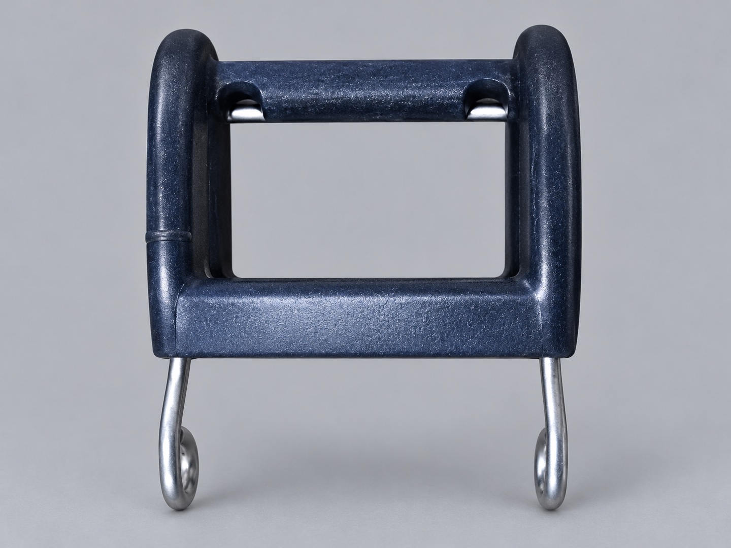
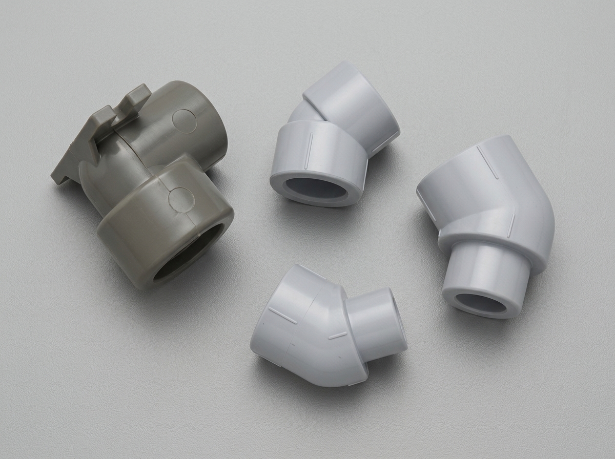
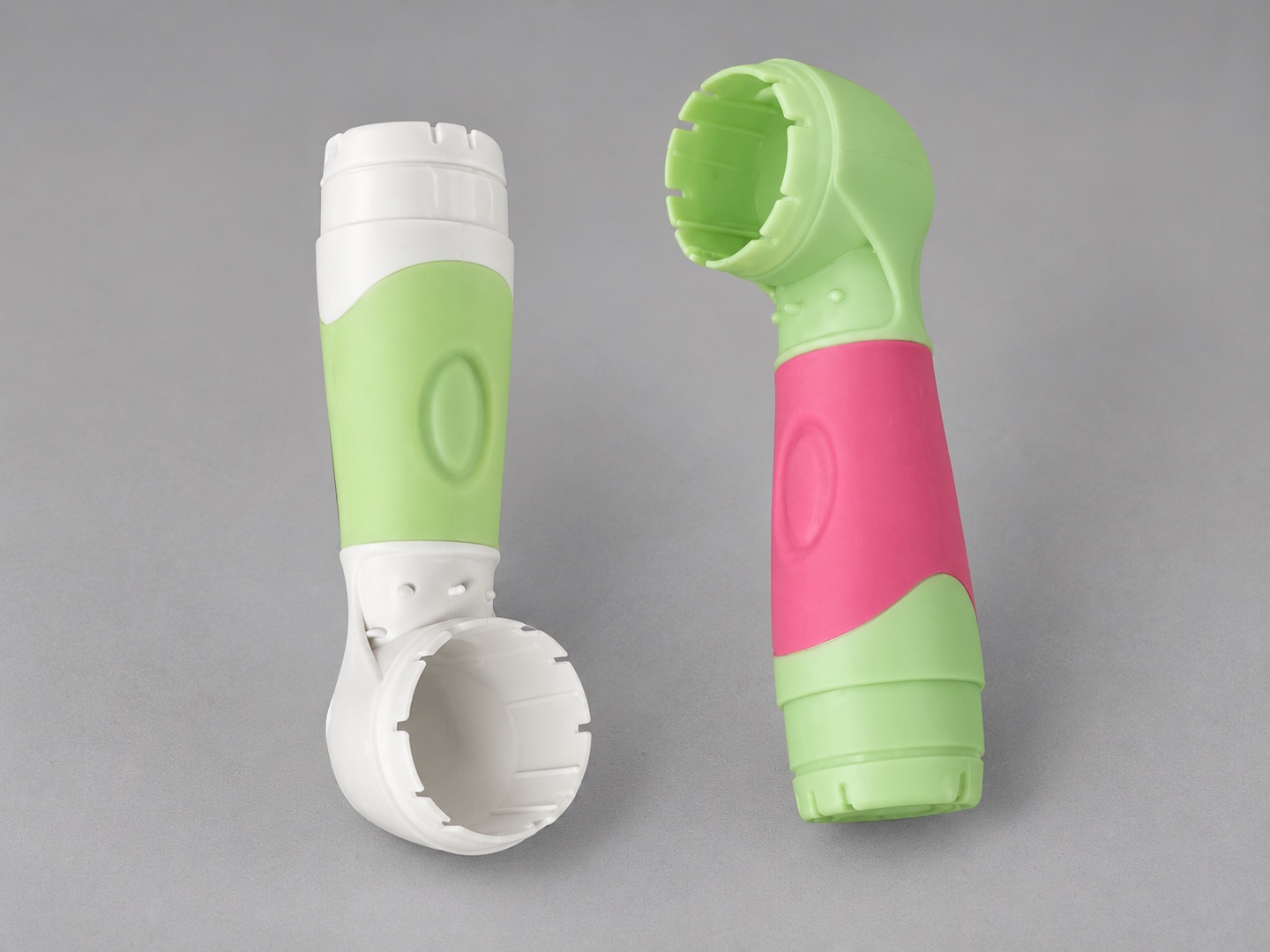
Explore related catalog parts. Images illustrate part types; confirm materials, dimensions and acceptance requirements for your project.
Customer-supplied inserts can be discussed. Share drawings, material and plating requirements, supply responsibility and available samples so the team can review fit and handling.
Insert sourcing and any required material or plating documentation can be discussed during quotation. Confirm the supplier, specifications and responsibilities before production.
Insert location, shut-off geometry and molding conditions are reviewed against the design. Thread protection and inspection requirements should be agreed before tooling.
Retention depends on insert geometry, plastic grade, part design and processing. Provide the required load and test method so the acceptance criteria can be agreed.
Share the application, drawing revision, material requirements, expected quantity and acceptance needs. Sensitive files can be exchanged after an NDA through a channel we agree together.
Request a Quote