
- Decouple velocity-controlled filling (95% to 98% cavity volume) from pressure-controlled packing: Transferring from 1st-stage velocity to 2nd-stage hold pressure too late (> 99% full) spikes cavity pressure above clamping force and causes parting-line flash; transferring too early (< 90%) causes short shots and sink marks.
- Perform a quantitative Gate-Seal Study on every T1 trial: Weigh parts at 1-second hold-time increments until part weight plateaus. Setting hold time shorter than gate freeze-off allows molten resin to back-flow out of the cavity, causing severe sink marks and dimensional drift (Cpk < 1.0).
- Distinguish moisture splay from shear splay before adjusting barrel heats: Hygroscopic moisture in PC, PA66, PBT, or ABS creates silver streaks across the entire surface (fix: dry resin to < 0.02% moisture), whereas gate shear splay radiates only around the gate orifice (fix: reduce initial fill velocity or enlarge gate depth).
- Warpage in glass-filled polymers (PA66-GF30) is driven primarily by anisotropic fiber orientation, not just cooling: Glass fibers align parallel to melt flow (shrinking 0.3%) while cross-flow shrinks 0.9% to 1.1%; use linear fan gating and balanced turbulent cooling (Re ≥ 4000) to flatten panels.
- Verify clamping tonnage using projected cavity area (F_clamp ≥ A_proj × P_cavity × 1.2): Insufficient press tonnage allows the mold halves to breathe open by 0.03 to 0.08 mm during pack peak, flashing parting lines and shifting non-mold-bound tolerances.
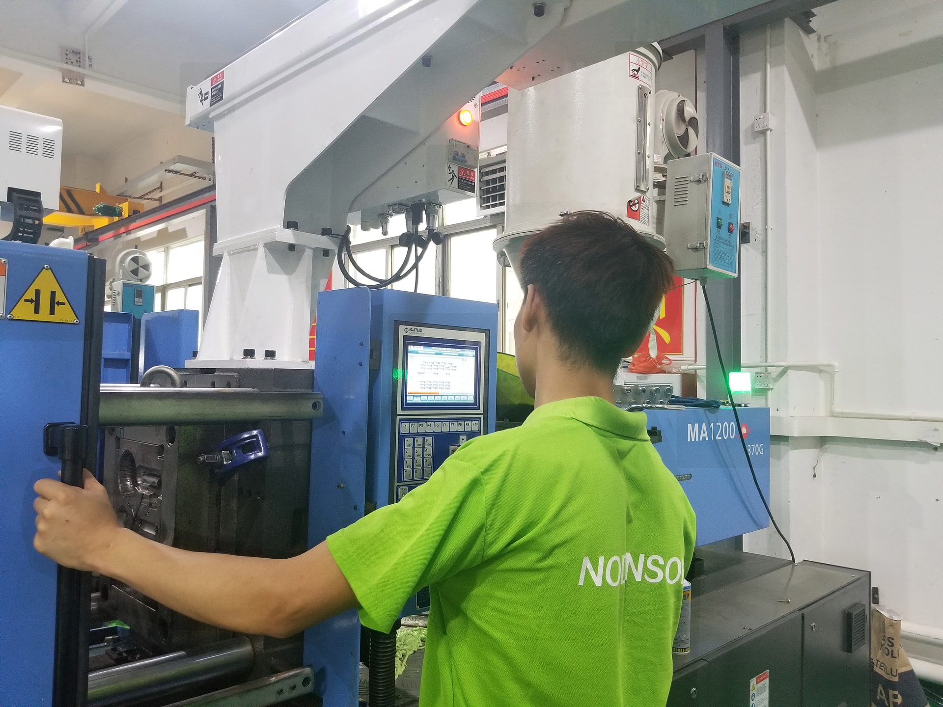
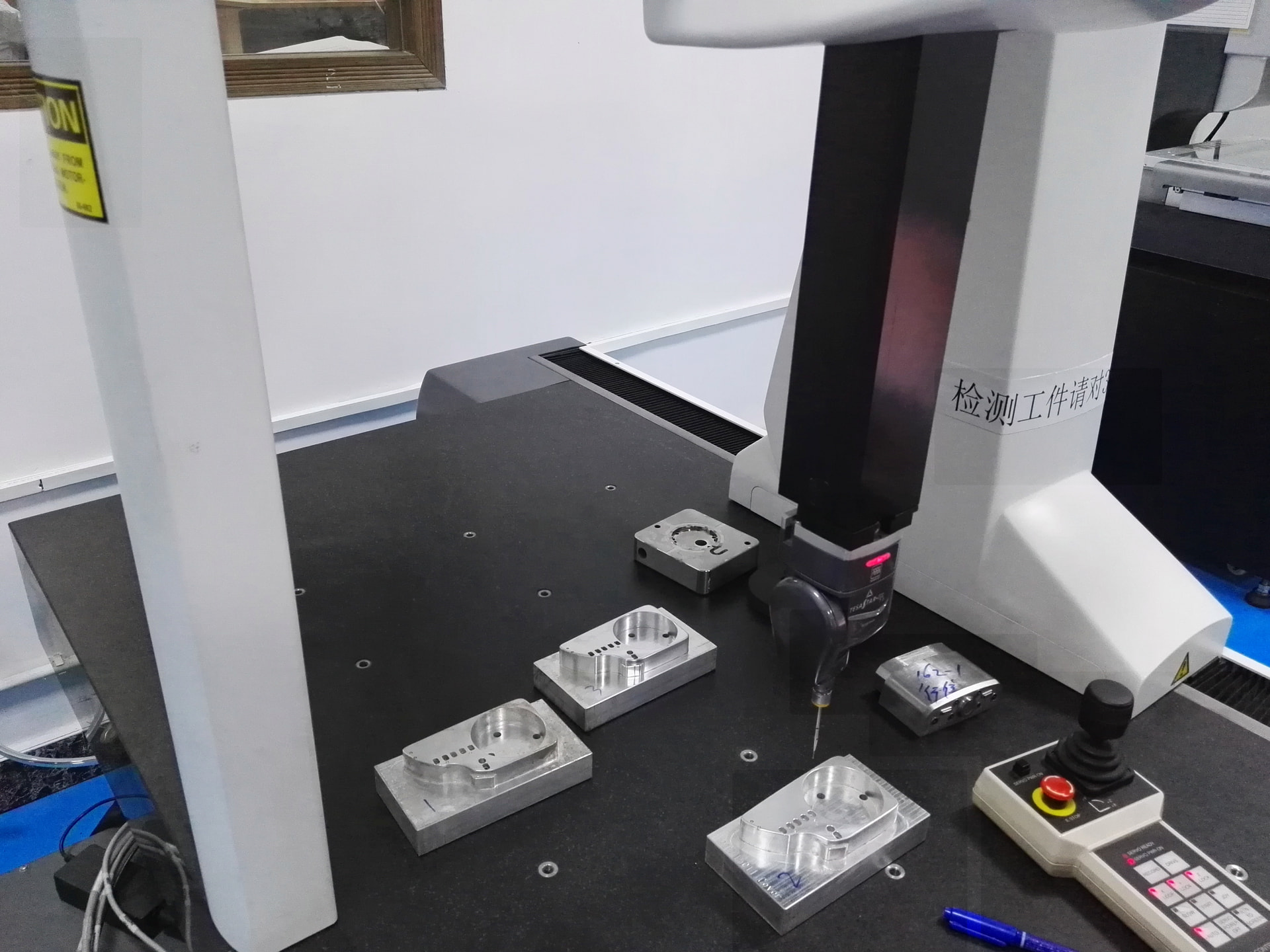
How Does Scientific (Decoupled) Molding Eliminate Process Variability from the Plastics Viewpoint?
Scientific Molding (Decoupled II & III processing) controls injection molding from the physical perspective of the polymer inside the cavity—using four fundamental plastic variables: Melt Temperature, Melt Flow Rate (Shear Viscosity), Cavity Packing Pressure, and Cooling Rate—rather than relying on machine-specific hydraulic settings. Under ISO 294 injection molding standards, separating the filling phase from the packing/holding phase establishes a wide, repeatable process window.
- η_effective = Relative in-mold apparent viscosity (MPa·s); plotted against shear rate (1/t_fill) to find the flat shear-thinning plateau
- V/P Transfer Point = Screw position where cavity is 95% to 98% volumetrically filled (verified by pulling a 0-hold-pressure "short shot" sample)
- A_projected = Total projected surface area of all cavities + cold runners on the parting plane (cm²)
- P_cavity = Average in-cavity packing pressure (typically 300 to 500 kgf/cm² for PP/ABS; 500 to 800 kgf/cm² for thin-wall PC and PA66-GF30)
What Is the Engineering Root-Cause Matrix for the 8 Major Injection Molding Defects?
Every cosmetic or structural defect on an injection molded part stems from an interaction between part DFM geometry, mold tooling construction, polymer preparation, and decoupled machine parameters. Use the diagnostic matrix below to isolate the true physical root cause before modifying tooling or process settings:
| Molding Defect | Physical Root Cause | Scientific Process Countermeasure | Tooling & Part DFM Fix |
|---|---|---|---|
| Sink Marks & Vacuum Voids | Localized thick thermal mass (rib/boss root) shrinks after gate freezes or skin hardens | Extend hold time until gate-seal plateau; increase pack pressure; maintain 3–5 mm melt cushion | Reduce rib base to 0.50–0.60T; enlarge gate depth to 0.75T |
| Part Warpage & Bowing | Differential shrinkage due to core-cavity ΔT, uneven packing, or glass-fiber orientation | Balance core/cavity coolant ΔT within ≤ 2°C; use multi-stage stepped packing profile to reduce gate over-pack | Add conformal cooling / BeCu core pins; switch pinpoint gate to linear fan gate |
| Weak or Visible Weld Lines (Knit Lines) | Two cooled melt fronts meet at low angle (< 135°) with trapped air inhibiting molecular entanglement | Increase 1st-stage injection velocity; raise mold wall temperature (+15°C); increase melt temperature | Machine 0.015–0.025 mm perimeter vents or add a sacrificial overflow tab at the weld junction |
| Parting-Line & Ejector Flash | Late V/P transfer spikes cavity pressure above clamp force, or worn shut-off land gap > 0.02 mm | Shift V/P transfer earlier to 96% fill; lower 2nd-stage pack pressure; increase press clamping tonnage | Blue-spot fit parting shut-offs on spotting press; add hardened support pillars under B-plate |
| Short Shots (Incomplete Fill) | Premature skin freeze-off in thin ribs, air-lock backpressure, or pressure-limited injection | Verify press is not pressure-limited during 1st stage; increase fill velocity onto viscosity plateau | Deepen end-of-fill vents; add flow leader ribs (+0.3 mm wall) along long flow paths |
| Silver Streaks (Splay Marks) | Vaporized moisture bubbles (hygroscopic resins), thermal resin degradation, or gate shear air entrapment | Verify desiccant dryer dew point (-40°C) & moisture (< 0.02%); use profiled slow-fast-slow fill velocity | Enlarge restrictive gate orifice; polish sharp runner transitions to reduce shear heating |
| Diesel Burn Marks (Black Scorching) | Trapped air pocket compressed adiabaticly to > 400°C auto-ignition at end of fill or blind rib | Reduce final-stage fill velocity (profiled deceleration from 85% to 98% stroke); lower clamp tonnage slightly | Add vented ejector pins, porous sintered metal inserts, or 0.02 mm parting vents at air trap |
| Jetting & Tiger Stripes | High-velocity melt stream shoots unobstructed through gate or oscillates dynamically during fill | Use slow-to-fast stepped velocity profile until melt front passes gate zone; warm up mold steel | Overlap gate against a core wall (impingement gating) or switch to fan/tab gate |
Every production tool built at Nodinson ships with a documented Scientific Molding Process Setup Sheet, Gate-Seal Curve, T1 Trial Video, and 3D CMM First Article Inspection Report.
How Do You Conduct the 3 Core Scientific Molding Qualification Studies at T1 Trial?
Before approving any injection mold for mass production or export shipment, Nodinson molding engineers execute three standardized empirical qualification studies on our Haitian servo-hydraulic presses:

- 1. In-Mold Rheology (Viscosity Curve) Study: With 2nd-stage pack pressure set to zero, parts are shot across 6 to 8 injection velocities (from 10 mm/s to 150 mm/s). Recording fill time (
t_fill) and peak intensification pressure establishes the shear-thinning knee—identifying the optimal injection speed where viscosity is flat and insensitive to minor lot-to-lot resin variation. - 2. Multi-Cavity Balance Study (Short-Shot Method): For 2-, 4-, 8-, or 16-cavity molds, short shots at 50%, 80%, and 95% fill volume are weighed on a 0.01 g analytical scale. Naturally balanced runners must exhibit < 2.5% weight variation across all cavities before holding pressure is applied.
- 3. Gate Freeze-Off (Gate Seal) Study: Holding pressure is applied in 1.0-second increments (1s, 2s, 3s, 4s... 10s), and part weights are plotted. Once part weight stops increasing, the gate is 100% frozen solid; we lock production hold time at Gate Freeze Time + 1.0 second safety margin.
Even on a 250-ton press, if a multi-cavity mold lacks sufficient support pillars inside the ejector housing box behind the B-plate, cavity packing pressure will deflect the center of the B-plate backward by 0.04 to 0.07 mm! That elastic deflection causes cavities near the sprue bush to flash while outer cavities remain short. Always space hardened support pillars (pre-loaded +0.02 mm above spacer blocks) across the full ejector box span.
Frequently Asked Questions on Injection Molding Defects & Troubleshooting
Why does increasing holding pressure sometimes make part warpage worse?
Excessive holding pressure over-packs the region immediately surrounding the gate while the distal end of the part has already cooled at lower pressure. This creates a severe internal density and residual stress gradient between the gate zone and end-of-fill, causing the part to twist or saddle-warp after ejection. Using a stepped high-to-low packing pressure profile relieves gate-area over-packing.
What is the difference between a Sink Mark and a Vacuum Void?
Both are caused by uncompensated volumetric thermal contraction in a thick section, but their manifestation depends on outer skin rigidity. If the outer plastic skin is warm and pliable (high mold temperature, slow cooling), atmospheric pressure pushes the skin inward to form a surface sink mark. If the outer skin freezes into a rigid shell immediately (cold mold, glass-filled resin), the contracting core pulls away from the center to form an internal vacuum bubble (void).
How do you eliminate weld lines on parts with multiple holes or bosses?
Whenever a melt front splits around a core pin and recombines on the far side, a weld line is physically unavoidable. However, you can make the weld line structurally invisible and reach 90%+ bulk strength by increasing melt and mold temperatures, venting the weld zone, or using sequential valve gating so a single continuous melt front sweeps past the core pin before the second gate opens.
How do I verify if resin moisture is causing brittle parts in Polycarbonate or Nylon?
When hygroscopic polymers like PC, PBT, PET, or PA66 are molded with moisture content above 0.02% (PC) or 0.15% (PA66), high barrel temperatures trigger hydrolysis—chemically severing long polymer chains and reducing molecular weight by 30%+. Parts may look normal or show slight silver splay, but they shatter like glass under impact. Always verify resin dryness with a Karl Fischer or loss-on-drying moisture analyzer prior to molding.

Authoritative Standards & Engineering References
- ISO 294-1:2017: Plastics — Injection Moulding of Test Specimens of Thermoplastic Materials — General Principles and Molding Window Qualification.
- ISO 20457:2018 / DIN 16742: Plastics Moulded Parts — Dimensional Tolerances, Warpage & Acceptance Conditions.
- Society of Plastics Engineers (SPE): Scientific Molding Pocket Guide & Decoupled Processing Standards (Routsis / RJG Methodology).
- ASTM D6980: Standard Test Method for Determination of Moisture in Plastics by Loss in Weight.