
- Maintain uniform nominal wall thickness within ±15% across the entire part: Abrupt wall transitions generate differential volumetric shrinkage, internal shear stress, and bowl-shaped warpage. Always use a 3:1 gradual taper ramp when transitioning wall thickness.
- Limit structural rib base thickness to 50% to 60% of the nominal wall (T_rib = 0.50 to 0.60 × T_wall): Exceeding 65% creates a heavy thermal mass junction (inscribed circle diameter > 1.25T) that pulls sink marks onto the opposite cosmetic A-surface.
- Calculate draft angle by combining depth draft plus VDI 3400 texture compensation: Apply at least 1.0° to 1.5° base draft on untextured walls, and add +1.0° to 1.5° per 0.025 mm (0.001 in) of texture etch depth to prevent drag marks during ejection.
- Keep shut-off (kiss-off) angles at 3° to 5° minimum (7° preferred): Creating clip hook apertures via core-to-cavity sliding shut-offs eliminates expensive lateral cam slides, provided the steel contact land is angled at ≥ 3° to prevent galling.
- Select cam slides for exterior undercuts and angled lifters for internal undercuts: Horn-pin driven mechanical slides handle deep external features up to 40 mm, whereas internal clip hooks require 8° to 15° angled lifters riding on the ejector plate.
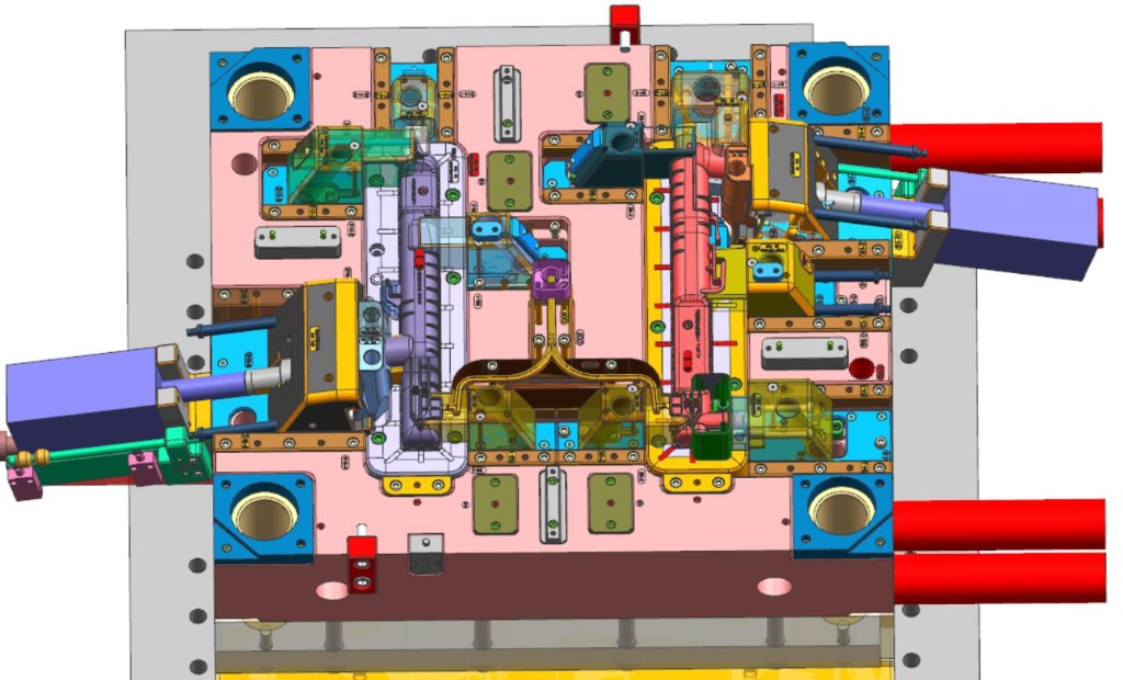
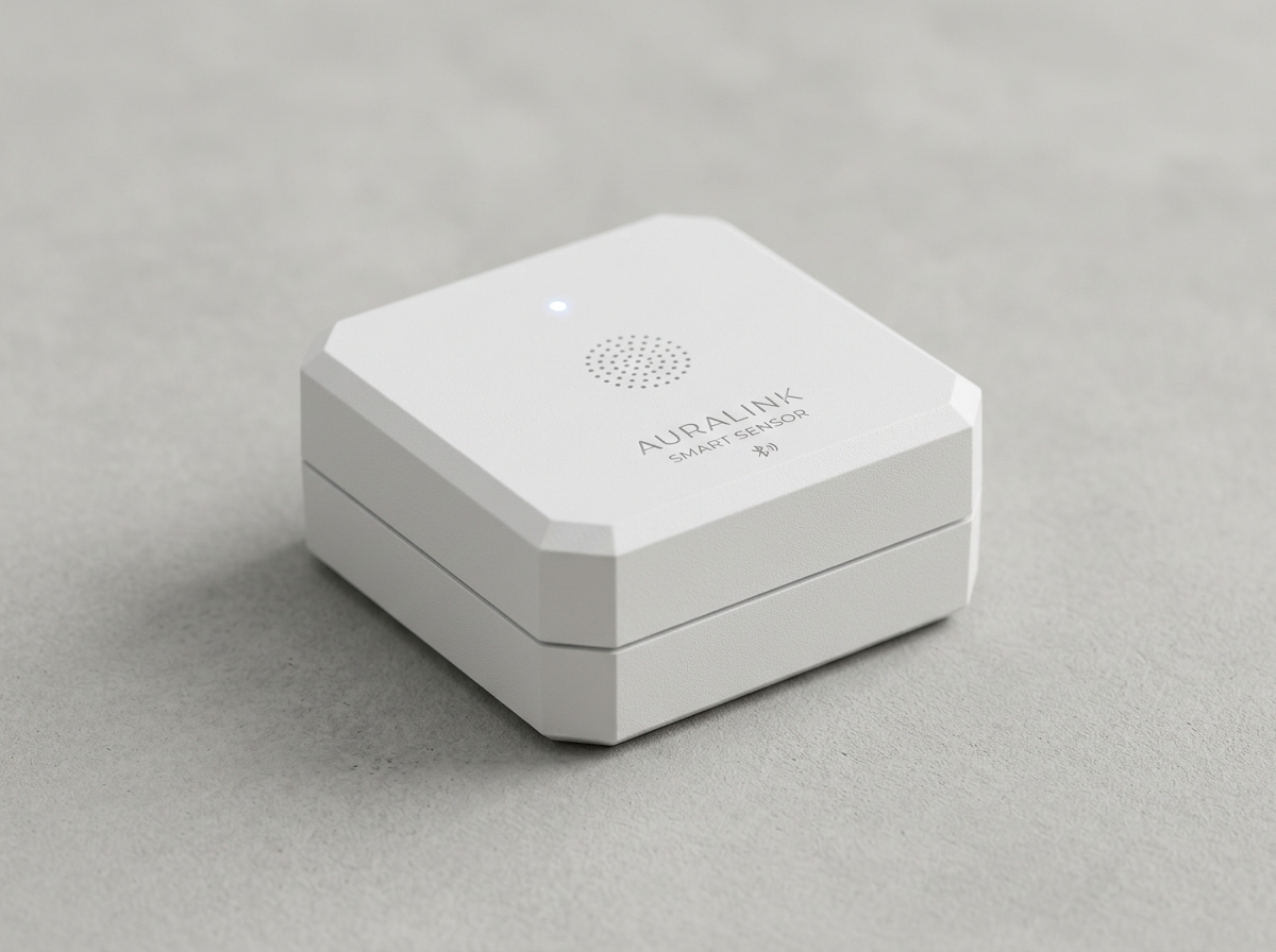
What Is the Optimal Nominal Wall Thickness for Different Engineering Thermoplastics?
The optimal nominal wall thickness for injection molded parts ranges between 1.2 mm and 3.5 mm depending on polymer melt viscosity, flow-length-to-wall-thickness ratio (L/T), and structural stiffness requirements. Keeping wall thickness uniform within ±10% to ±15% ensures balanced cavity filling, eliminates hesitation marks, and minimizes cooling cycle time, which scales with the square of wall thickness (h²) under ISO 20457 / DIN 16742 guidelines.
Every thermoplastic resin has a physical flow-length-to-thickness ratio (L/T limit) governed by shear viscosity and skin freezing rate. Attempting to fill a 180 mm electronic housing with a 1.0 mm wall in high-viscosity Polycarbonate (L/T ≈ 90:1) will result in short shots, extreme injection pressure (> 180 MPa), and severe molded-in residual stress.
| Thermoplastic Resin | Recommended Wall Thickness (mm) | Min. Thin-Wall Limit (mm) | Max. Flow Ratio (L / T) | Volumetric Shrinkage (%) | Primary DFM Caution |
|---|---|---|---|---|---|
| ABS (Standard & High-Impact) | 1.5 to 3.2 mm | 1.1 mm | 140 : 1 | 0.4% to 0.7% | Prone to gloss differentials and sink marks if rib root exceeds 0.60T |
| Polycarbonate (PC) | 1.8 to 3.5 mm | 1.2 mm | 85 : 1 to 100 : 1 | 0.5% to 0.7% | High melt viscosity; avoid sharp internal corners (keep R_in ≥ 0.5T) to prevent notch cracking |
| PC / ABS Alloy | 1.5 to 3.2 mm | 1.1 mm | 110 : 1 to 130 : 1 | 0.4% to 0.6% | Ideal for electronic enclosures; keep shear rate below 40,000 s⁻¹ at the gate |
| PA66 + 30% Glass Fiber | 1.5 to 3.0 mm | 0.9 mm | 130 : 1 to 160 : 1 | 0.3% (Flow) / 0.9% (Cross) | Anisotropic fiber orientation causes warpage if wall thickness varies across the part |
| POM (Acetal Homopolymer / Copolymer) | 1.2 to 3.0 mm | 0.8 mm | 150 : 1 | 1.8% to 2.4% | High crystalline shrinkage; requires uniform coring on precision gear webs and hubs |
| PBT + 30% GF (Electrical Connectors) | 1.0 to 2.5 mm | 0.6 mm | 140 : 1 | 0.3% to 0.8% | Rapid crystallization freezes thin pin barriers quickly; vent dead-end pockets at 0.015 mm |
| Polypropylene (PP) | 1.2 to 3.5 mm | 0.8 mm | 200 : 1 to 250 : 1 | 1.2% to 2.2% | Living hinges require 0.25 to 0.35 mm web thickness with perpendicular flow orientation |
How Do You Calculate Rib-to-Wall Ratios and Boss Geometry to Eliminate Sink Marks?
To eliminate cosmetic sink marks, the rib base thickness (T_rib) must be 50% to 60% of the nominal wall thickness (T_wall), rib height must not exceed 2.5 to 3.0 times T_wall, and the root fillet radius must stay between 0.25 and 0.40 times T_wall. Instead of designing one thick rib for bending stiffness, space multiple thin ribs at a minimum center-to-center pitch of 2.5 × T_wall.
When a rib intersects a flat wall, it forms a localized T-junction whose effective thermal mass is defined by the inscribed circle diameter (D_inscribed). Because the core of that inscribed circle cools slower than the surrounding frozen skin, volumetric contraction pulls the warmer cosmetic outer skin inward, creating a visible depression (sink mark) exceeding 15 to 40 µm depth.
- T_rib = Rib thickness measured at the base intersection above the root fillet (mm) (Use 0.50T for high-gloss SPI A1/A2 surfaces; 0.60T for textured VDI surfaces)
- D_inscribed ≤ 1.25 · T_wall = Maximum allowable inscribed circle at the rib-wall T-junction to prevent visible sink
- H_rib ≤ 3.0 · T_wall = Maximum rib height before deep EDM slot venting and core ejection drag become problematic
- S_pitch ≥ 2.5 · T_wall = Minimum spacing between parallel ribs to allow adequate mold steel cooling conduction
| Structural Feature | Design Parameter | Standard Formula / Rule | Example (for 2.5 mm Nominal Wall) |
|---|---|---|---|
| Stiffening Rib Base | Base Thickness (T_rib) | 0.50 to 0.60 × T_wall | 1.25 to 1.50 mm base thickness |
| Stiffening Rib Height | Total Height (H_rib) | 2.5 to 3.0 × T_wall | 6.25 to 7.50 mm max height |
| Rib Draft Angle | Per Side Taper (θ_rib) | 0.5° to 1.0° per side | 0.5° (~0.06 mm taper per side over 7 mm height) |
| Screw Boss Wall | Outer Boss Wall (T_boss) | 0.60 × T_wall around cored hole | 1.50 mm wall; reinforce with 4 triangular gusset ribs |
| Corner Radii | Inside (R_in) & Outside (R_out) | R_in = 0.5 × T_wall; R_out = R_in + T_wall | R_in = 1.25 mm; R_out = 3.75 mm (Constant wall bend) |
Never merge a cylindrical screw boss directly into an exterior cosmetic sidewall! That creates a thick localized section that guarantees an external sink mark and a vertical shadow line. Always offset the screw boss at least 3.0 to 4.0 mm inset from the outer wall and bridge it to the sidewall using a thin 0.50T connecting gusset rib.
Upload your 3D STEP model for a color-coded wall thickness, draft angle, parting line, and undercut slide analysis before committing to mold steel.
How Much Draft Angle Is Required for Textured Cavities, Deep Ribs, and Core Shut-Offs?
Every vertical surface parallel to the mold opening direction requires a minimum 1.0° to 1.5° base draft angle for untextured surfaces, plus an additional 1.0° to 1.5° of draft for every 0.025 mm (25 µm) of chemical etch or VDI 3400 spark-erosion texture depth. For core-to-cavity sliding metal shut-offs (kiss-offs), a minimum 3.0° to 5.0° angle is mandatory to prevent steel galling.
As molten plastic cools inside the mold, volumetric shrinkage causes the part to clamp tightly onto internal mold cores. Without sufficient draft angle, the part must be dragged along the full vertical height of the core during ejection—resulting in white ejector stress marks, part distortion, or deep scrape scratches across textured cosmetic faces.
- θ_total = Minimum required draft angle per side (°)
- d_texture = Peak-to-valley surface texture depth (mm) per VDI 3400 or Mold-Tech specification
- Δx = Horizontal wall taper offset over feature depth H_depth (e.g., at 2° draft over 30 mm depth, Δx = 30 · tan(2°) = 1.05 mm per side)
- θ_shutoff ≥ 3.0° to 5.0° = Minimum metal-to-metal sliding shut-off angle for pass-through clip windows
How Do You Choose Between Pass-Through Shut-Offs, Cam Slides, and Angled Lifters for Undercuts?
When a plastic part contains lateral features (snap-fit hooks, side connector ports, or O-ring grooves) that block straight pull-out ejection, mold engineers resolve the undercut using one of three mechanisms: core-cavity pass-through shut-offs ($0 added mechanism cost), horn-pin driven mechanical cam slides (external undercuts), or angled ejector lifters (internal undercuts).
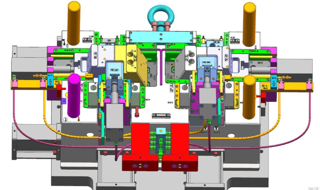

| Undercut Mechanism | Target Undercut Location | Max. Undercut Travel (S) | Tooling Cost Impact | Key Kinematic Design Rule |
|---|---|---|---|---|
| Pass-Through Core Shut-Off (Kiss-Off) | Internal clip hooks or side windows accessible from bottom | Unlimited (Formed by straight core projection) | Zero (+0%) — Most economical DFM solution | Requires a through-slot in the base wall below the clip and ≥ 3° to 5° shut-off angle |
| Mechanical Cam Slide (Horn Pin) | Exterior side ports, bosses, and perimeter recesses | 3.0 to 35.0 mm (Horn pin angle ≤ 22°) | Moderate (+8% to +15%) per slide assembly | Horn pin angle α must be 2° to 3° less than locking heel block angle (β = α + 2°) |
| Hydraulic Core-Pull Cylinder | Long side-cores, deep pipe bores, or pre-ejection pulls | 35.0 to 150.0+ mm | Moderate-High (+12% to +20%) | Equipped with proximity stroke sensors and hardened wedge locks to resist cavity pressure |
| Angled Ejector Lifter | Internal enclosure snap-fits and recessed inner undercuts | 1.0 to 8.0 mm (Lifter angle 8° to 15°) | Low-Moderate (+6% to +12%) | Lateral clearance S = L_eject · tan(θ_lifter); requires clear internal space to move inward |
An angled lifter releases an internal undercut by translating horizontally inward as the ejector plate pushes forward. If you place a structural rib, screw boss, or PCB mounting post directly behind the lifter travel path, the lifter head will collide with the plastic feature during ejection! Always leave a clear inward travel zone of at least Undercut Depth + 2.5 mm behind every internal snap-fit hook.
Frequently Asked Questions on Injection Molding DFM Design
Can I design a zero-draft (0°) vertical wall on an injection molded part?
Zero-draft walls are strongly discouraged because polymer shrinkage clamps the part onto the steel core, causing ejection drag marks and high demolding forces. If a functional mating bore or bearing surface strictly requires 0° vertical walls, we must utilize a dedicated sleeve ejector pin, polished S136 draw-polished core steel, or a retreating cam slide—which adds tooling complexity.
How do I eliminate a side cam slide on an internal snap-fit hook?
Open a pass-through aperture directly underneath the snap-fit overhang so a vertical core pin extending from the bottom mold half can form the underside of the hook and shut off against the top cavity steel at a 3° to 5° angle. This simple CAD modification eliminates the need for an internal angled lifter or side action.
Why are uniform corner radii so important in plastic injection molding?
Sharp internal corners (R < 0.2 mm) act as severe mechanical stress concentrators (notch factor K_t > 3.0) and cause turbulent shear heating as molten plastic turns the corner. Designing an inside radius of 0.5 × T_wall and an outside radius of 1.5 × T_wall maintains a constant wall thickness around the bend, improving impact strength by over 300%.
What happens during Nodinson’s 24-hour DFM review before mold making?
Every project undergoes a systematic 24-hour DFM audit where our engineers generate a visual slide deck covering 3D wall-thickness heatmaps, draft angle color plots, parting line and gate proposals, ejector pin witness locations, and steel/tolerance recommendations (DIN 16742) for customer sign-off before steel is ordered.

Authoritative Standards & Engineering References
- ISO 20457:2018 / DIN 16742: Plastics Moulded Parts — Tolerances, Wall Thickness & Acceptance Conditions.
- VDI 3400 Guideline: Surface Texture & Required Draft Angle Compensation in Spark Erosion Tooling.
- Plastics Industry Association (SPI): Design for Manufacturability Guidelines for Thermoplastic Injection Molding.
- Society of Plastics Engineers (SPE): Injection Molding Handbook — Part Geometry, Rib Design & Mold Kinematics.