
- DIN 16742 and ISO 20457:2018 define 9 distinct Tolerance Groups (TG1 to TG9) based on resin chemistry, part geometry, and manufacturing precision.
- Mold-bound dimensions (formed within a single tool half) reliably achieve TG3 to TG4 (±0.05 mm to ±0.10 mm for dimensions ≤ 30 mm). Non-mold-bound dimensions (crossing parting lines, slides, or lifters) require wider tolerance bands of TG5 to TG6 (±0.12 mm to ±0.20 mm) due to machine clamp pressure variation and mechanical clearance.
- Amorphous polymers (ABS, PC, PC/ABS) exhibit isotropic, predictable shrinkage (0.4% to 0.7%). In contrast, semi-crystalline polymers (POM, PA66, PBT) exhibit high anisotropic shrinkage (1.5% to 2.5%) strongly aligned with flow orientation and wall thickness differences.
- The "Steel-Safe" design rule is essential for critical fits: design mold cores slightly oversized (+0.05 mm) and cavity recesses slightly undersized (-0.05 mm). This ensures final adjustments after T0 sampling can be dialed in via sub-micron EDM or CNC shaving rather than costly laser welding.
- Never apply metal machining tolerances (ISO 2768-m) directly to plastic drawings. Plastic shrinks dynamically as it cools and absorbs ambient humidity over 24 to 48 hours post-molding.
What Is the Difference Between DIN 16742 and ISO 20457 Standards?
DIN 16742 and ISO 20457:2018 are identical modern engineering standards specifically developed for injection molded plastic part tolerances, replacing obsolete metal standards like ISO 2768. They establish nine tolerance groups (TG1 to TG9) based on resin chemistry, part dimensions, and tool construction, distinguishing between rigid mold-bound features and dynamic non-mold-bound parting line clearances.
Historically, designers relied on DIN 7710 and general metal tolerances (such as ISO 2768-m). However, plastics behave in fundamentally different ways compared to metals: polymers exhibit high thermal expansion coefficients (5 to 10 times higher than steel), viscoelastic creep under stress, and post-demolding crystallization shrinkage.
In 2013, the German Institute for Standardization published DIN 16742 (Plastics moulded parts: Tolerances and acceptance conditions), replacing older standards. In 2018, this was standardized globally as ISO 20457:2018. Both standards classify plastic component tolerances into 9 Tolerance Groups (TG1 to TG9):
TG1 to TG3: Precision engineering tolerances achievable only with tight-tolerance mold making, premium engineering resins (PC, PEEK), closed-loop servo injection presses, and strict temperature control.
TG4 to TG6: Standard commercial technical tolerances for electronic enclosures, consumer appliances, and automotive interior bezels.
TG7 to TG9: Wide commercial tolerances for flexible, high-shrinkage commoditized plastics (PE, PP, soft PVC).
How Do DIN 16742 Tolerance Groups Scale Across Nominal Dimensions?
DIN 16742 tolerance groups scale proportionally with nominal dimensions to account for volumetric thermal contraction during polymer solidification. High-precision engineering polymers in TG3 achieve bilateral tolerances from ±0.04 mm for dimensions under 6 mm to ±0.23 mm at 250 mm, whereas standard commercial technical components in TG5 range from ±0.10 mm to ±0.50 mm across the same size envelope.
The table below outlines achievable symmetric bilateral tolerances (± mm) for mold-bound dimensions across key nominal size brackets:
| Nominal Dimension (mm) | TG3 (High Precision) | TG4 (Precision Technical) | TG5 (Standard Commercial) | TG6 (Economy Technical) | TG7 (Wide Tolerance) |
|---|---|---|---|---|---|
1 < L ≤ 6 mm | ±0.04 mm | ±0.06 mm | ±0.10 mm | ±0.15 mm | ±0.24 mm |
6 < L ≤ 18 mm | ±0.05 mm | ±0.08 mm | ±0.12 mm | ±0.18 mm | ±0.28 mm |
18 < L ≤ 30 mm | ±0.06 mm | ±0.09 mm | ±0.15 mm | ±0.22 mm | ±0.35 mm |
30 < L ≤ 50 mm | ±0.08 mm | ±0.12 mm | ±0.19 mm | ±0.28 mm | ±0.45 mm |
50 < L ≤ 80 mm | ±0.11 mm | ±0.16 mm | ±0.24 mm | ±0.36 mm | ±0.56 mm |
80 < L ≤ 120 mm | ±0.14 mm | ±0.21 mm | ±0.31 mm | ±0.46 mm | ±0.70 mm |
120 < L ≤ 180 mm | ±0.18 mm | ±0.27 mm | ±0.40 mm | ±0.60 mm | ±0.90 mm |
180 < L ≤ 250 mm | ±0.23 mm | ±0.34 mm | ±0.50 mm | ±0.75 mm | ±1.15 mm |
Why Do Non-Mold-Bound Dimensions Have Wider Tolerances?
Non-mold-bound dimensions require wider tolerance bands because they cross dynamic tool splits such as main parting lines, side-action slides, or angled lifters. While mold-bound features rely solely on rigid cavity steel accuracy, non-mold-bound features accumulate machine platen breathing under high injection pressures (0.02 to 0.05 mm), mechanical gib clearances (0.02 mm), and thermal expansion variance between core and cavity blocks.
In injection mold engineering, dimensional features are strictly categorized into two structural classes:
1. Mold-Bound Dimensions (Tooling Cavity Bound)
A feature formed entirely within the fixed cavity or the moving core block alone. Because the steel geometry is rigid and does not move during injection pressure, the only tolerances involved are tool manufacturing accuracy (±0.005 mm) and polymer volumetric shrinkage variation (±0.05%). These dimensions reliably achieve TG3 or TG4.
2. Non-Mold-Bound Dimensions (Parting Line & Slide Crossing)
Any feature formed across two mating tooling components: across the primary parting line (PL), between a slide and the core, or between dynamic angled lifters and cavity blocks. Non-mold-bound features accumulate mechanical clearances:
- Platen deflection & clamping variability: Under 150 to 300 tons of clamp force, mold platen breathing introduces 0.02 to 0.05 mm of axial variance.
- Slide lock wear: Mechanical clearances on slide guide gibs and heel blocks require 0.015 to 0.03 mm operational play.
- Thermal expansion differences: Temperature differences between the core and cavity (often 10°C to 20°C) cause differential linear thermal growth of tool blocks.
When detailing drawings for automated assembly parts, never assign the same bilateral tolerance to both depth and height if one dimension crosses the mold parting line. If an internal pocket depth is held to ±0.06 mm (mold-bound), widen the overall external part thickness across the parting line to ±0.12 mm (non-mold-bound) to avoid unreasonable mold clamping reject rates.
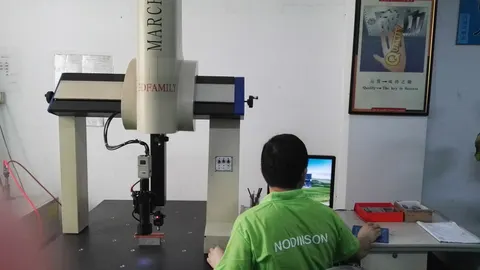
Submit your 2D PDF print with critical ballooned dimensions alongside your 3D STEP file. Our metrology team reviews resin shrinkage feasibility against DIN 16742 TG3/TG4 standards under bilateral NDA.
How Does Polymer Crystallinity Drive Anisotropic Shrinkage and Warpage?
Polymer crystallinity drives anisotropic shrinkage because semi-crystalline resins (POM, PA66) form ordered lamellar structures with high volumetric contraction (1.5% to 2.5%), compared to amorphous resins (ABS, PC) with random polymer chains and isotropic shrinkage (0.4% to 0.7%). In glass-reinforced resins, differential shrinkage between parallel fiber flow and perpendicular matrix cooling creates severe internal stress and out-of-plane warpage.
Polymers do not shrink uniformly in all three spatial dimensions. Shrinkage behavior is dictated by polymer morphology:
| Polymer Family | Examples | Morphology | Shrinkage Rate (%) | Shrinkage Anisotropy |
|---|---|---|---|---|
| Amorphous | ABS, PC, PC/ABS, PMMA, SAN | Random entangled chains | 0.4% to 0.7% | Isotropic (Uniform in all directions) |
| Semi-Crystalline (Unfilled) | PP, PE, POM, PA6, PA66 | Ordered crystalline lamellae | 1.5% to 2.5% | High (Flow direction vs Transverse) |
| Fiber-Reinforced | PA66-GF30, PBT-GF20, PC-GF10 | Oriented glass fibers | 0.2% to 0.8% (Flow) / 0.8% to 1.5% (Transverse) | Extreme (2:1 to 3:1 ratio causing warpage) |
When molding fiber-reinforced resins (such as PA66-GF30), gate location directly dictates fiber alignment. Shrinkage parallel to melt flow is restricted by the stiff glass fibers (e.g., 0.3%), whereas shrinkage perpendicular to flow is governed by the matrix resin (e.g., 1.1%). This 3x differential shrinkage produces severe out-of-plane twist and warpage if not compensated in DFM.
How Does the "Steel-Safe" Tooling Principle Protect Tight Tolerances?
The steel-safe tooling principle protects tight tolerances by machining mold core pins slightly oversized (+0.05 mm) and cavity pockets slightly undersized (-0.05 mm). Because post-molding shrinkage cannot be modeled with 100% precision across complex 3D flow paths, this methodology guarantees that dimensional fine-tuning after T0 first-article sampling is achieved entirely by removing tool steel through CNC or EDM rather than expensive welding.
Because predicting the exact final shrinkage of complex three-dimensional geometry down to 0.01 mm is physically impossible due to pressure gradients and gate freezing dynamics, Nodinson implements the "Steel-Safe" Tooling Methodology:
1. For Outer Dimensions (Formed by Cavity Pockets): Steel must be left on the tool (cavity pocket machined slightly smaller than nominal, -0.05 mm). If the molded plastic part turns out too large after T0 trial, steel can easily be removed from the cavity using high-speed CNC milling or EDM spark erosion.
2. For Holes & Inner Features (Formed by Core Pins): Core pins are machined slightly larger than nominal (+0.05 mm). If the molded hole turns out too small, steel is easily ground off the core pin to enlarge the hole.
Specifying metal machining tolerances (such as ISO 2768-m or ±0.02 mm across all general features) on an injection molded drawing is the leading cause of tooling quote rejections and inflated costs. Steel does not shrink, absorb moisture, or relax internal stress at 25°C; plastic does. Always reference DIN 16742 or ISO 20457 to establish achievable, repeatable quality criteria.
This ensures that 100% of fine tolerance tuning after the First Article Inspection (FAI) report is executed by removing steel, entirely avoiding costly welding, insert patching, or mold block remanufacturing.
Frequently Asked Questions on Injection Molding Tolerances
Can injection molded plastic parts achieve CNC machining tolerances (±0.01 mm)?
No, not across broad production runs. While steel molds can be machined to ±0.003 mm, the plastic material itself expands and contracts with ambient factory temperature swings and humidity changes. A 50 mm POM part will change dimension by 0.015 mm simply from a 3°C temperature shift. For ±0.01 mm requirements, secondary CNC post-machining or metal insert molding is recommended.
How does moisture absorption affect PA6 and PA66 dimensions after molding?
Polyamides (Nylon 6 and 66) are hygroscopic. Immediately after molding (dry-as-molded), dimensions are at their smallest. Over several weeks, PA6 absorbs up to 2.5% to 3.0% atmospheric moisture, resulting in linear dimensional swelling of approximately 0.2% to 0.5%. Critical dimensions must be inspected either immediately dry or after standardized moisture conditioning (water bath annealing at 70°C).
How should DIN 16742 be specified on our 2D engineering drawing title block?
In the title block general tolerance note, state: "General Tolerances: DIN 16742, TG4 (or ISO 20457, TG4)". Critical press-fit diameters, snap-lock teeth, or PCB mounting bosses should carry explicit bilateral dimensional tolerances (e.g., Ø 12.00 ± 0.05 mm) rather than relying on general block tolerances.
What Cpk process capability is expected for DIN 16742 TG4 tolerances?
In automotive and industrial electronics, a process capability of Cpk ≥ 1.33 (or Cpk ≥ 1.67 for critical safety features) is standard. Meeting TG4 tolerances with Cpk ≥ 1.33 requires closed-loop injection velocity control, cavity pressure sensing transducers, and temperature-controlled tool manifolds.
Authoritative Tolerancing Standards & Metrology References
- DIN 16742:2013-10: Plastics moulded parts, Tolerances and acceptance conditions (Beuth Verlag).
- ISO 20457:2018: Plastics moulded parts, Tolerances and acceptance conditions (International Organization for Standardization).
- ISO 2768-1 / ISO 2768-2: General tolerances for linear and angular dimensions.
- VDI 2005 Guideline: Design and tolerance of technical plastic injection moulded parts.