
- Size gate depth to 50% to 80% of nominal wall thickness (h_gate = 0.50 to 0.80 × T_wall): Gate freeze-off time scales with the square of gate thickness. If the gate freezes before the cavity finishes packing, volumetric shrinkage cannot be compensated, causing severe sink marks and voids.
- Keep gate land length short at 0.50 to 0.80 mm: Excessive gate land length (> 1.2 mm) creates an exponential pressure drop (ΔP ∝ L_land), robbing holding pressure from the cavity.
- Never exceed the polymer critical wall shear rate (γ̇_max = 40,000 s⁻¹ for PC/ABS; 100,000 s⁻¹ for PP/PA): Excessive shear rate through a restrictive gate causes frictional shear heating (> 30°C spike), molecular chain scission, silver splay streaks, and brittle gate blush.
- Always use naturally balanced H-pattern runners for multi-cavity precision tools: Geometrically balanced runners guarantee identical flow path length and shear history to every cavity, whereas artificially balanced family runners shift balance whenever melt viscosity fluctuates.
- Hot runner systems reach financial break-even at 30,000 to 60,000 shots: By eliminating cold runner scrap (often 15% to 40% of shot weight when virgin resin is required) and cutting cycle time by 3 to 6 seconds, hot runners rapidly amortize their higher upfront manifold cost.
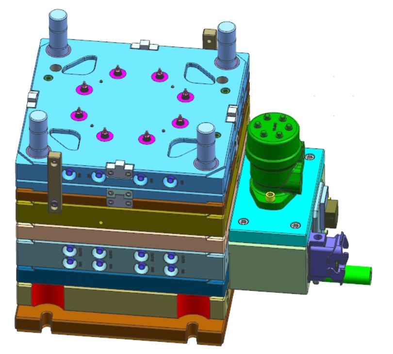
How Do Gate Shear Rate and Freeze-Off Time Govern Cavity Packing and Part Quality?
Gate shear rate (γ̇) and gate freeze-off time govern part quality by dictating whether molten polymer enters the cavity in a smooth laminar melt front without thermal degradation and remains open long enough to transmit holding pressure until the part core solidifies. Under ISO 11443 capillary rheometry standards, exceeding a resin's maximum allowable shear rate breaks polymer chains and ruins impact strength.
Because shear rate in a circular pinpoint or submarine gate is inversely proportional to the cube of the gate radius (R³), reducing a gate diameter by just 20% increases shear stress by nearly 200%!
- Q = Volumetric injection flow rate per gate (cm³/s or mm³/s)
- R = Radius of circular submarine, pinpoint, or valve gate (mm)
- W, H = Gate width (W) and gate depth (H = 0.50 to 0.80 × T_wall) for edge, fan, or tab gates (mm)
- n = Power-law shear-thinning index of the polymer (typically n = 0.25 to 0.35 for ABS/PA66; n = 0.65 to 0.80 for PC)
| Thermoplastic Polymer | Max Allowable Shear Rate (γ̇_max) | Gate Depth Ratio (H / T_wall) | Recommended Gate Land (L) | Defect Caused by Excessive Gate Shear |
|---|---|---|---|---|
| Polycarbonate (PC) | 35,000 to 40,000 s⁻¹ | 0.65 to 0.80 × T | 0.50 to 0.75 mm | Gate blush halo, black burn specks, severe loss of Izod impact resistance |
| ABS & PC/ABS | 40,000 to 50,000 s⁻¹ | 0.55 to 0.70 × T | 0.50 to 0.80 mm | Silver splay marks radiating from gate, delamination, gloss halo |
| POM (Acetal) | 40,000 to 45,000 s⁻¹ | 0.60 to 0.75 × T | 0.50 to 0.75 mm | Thermal decomposition releasing formaldehyde gas (corrodes mold steel & pits surface) |
| PA66 & PA6 (incl. GF30) | 60,000 to 90,000 s⁻¹ | 0.50 to 0.65 × T | 0.50 to 0.70 mm | Glass fiber breakage (reduces tensile modulus) & rapid abrasive gate wear |
| PBT + 30% GF | 50,000 to 70,000 s⁻¹ | 0.55 to 0.70 × T | 0.50 to 0.75 mm | Jetting worm-tracks and premature gate freeze preventing hold-pressure packing |
| PP & PE (Polyolefins) | 80,000 to 100,000 s⁻¹ | 0.45 to 0.60 × T | 0.50 to 0.75 mm | Tolerant to high shear; works well with small Ø 0.8–1.2 mm submarine gates |
How Do Submarine, Edge, Fan, Cashew, and Hot Valve Gates Compare?
Selecting the optimal gate geometry balances automatic degating automation, cosmetic vestige concealment, and packing pressure efficiency. While side edge gates and fan gates provide the widest packing window for thick or flat parts, submarine (tunnel) gates, cashew (banana) gates, and pneumatic/hydraulic valve gates automatically shear the runner during mold opening without manual trimming.
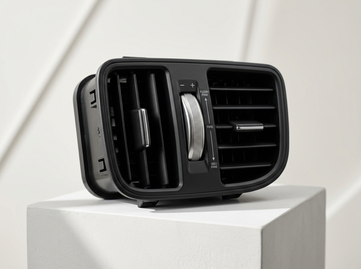
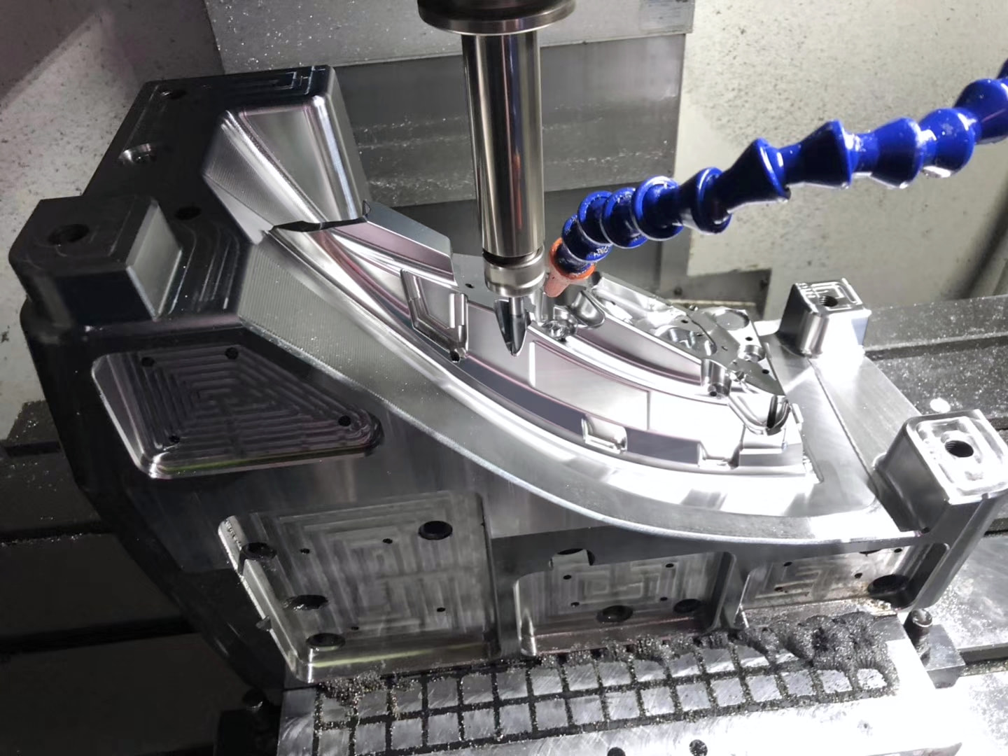
| Gate Type | Degating Method | Typical Gate Dimensions | Vestige Appearance | Best Engineering Application |
|---|---|---|---|---|
| Edge Gate (Side Gate) | Manual nipper or robotic degating fixture | Width 1.5–4.0 mm; Depth 0.60–0.75T; Land 0.6 mm | Rectangular witness mark on parting line edge (0.1–0.3 mm) | Flat enclosures, optical lenses, thick structural parts requiring extended hold packing |
| Fan Gate (Film Gate) | Robotic shear or CNC trim | Wide fan (up to full part width); Depth 0.40–0.60T | Long thin line along edge | Flat covers, LCD bezels, and glass-filled parts where linear planar flow prevents warpage |
| Submarine Gate (Tunnel Gate) | Automatic (Shears upon mold ejection) | Orifice Ø 0.8–1.8 mm; Tunnel angle 30°–45°; Taper 18°–22° | Small oval shear witness on side wall or internal ejector pin boss | High-volume electronic housings, connectors, and internal clips (2-plate mold automation) |
| Cashew Gate (Curved Tunnel) | Automatic (Flexes out of curved tunnel) | Orifice Ø 0.8–1.5 mm; 3D EDM curved arc underneath part | Completely hidden on underside B-surface of part | Cosmetic consumer electronics and instrument bezels where all 4 exterior sides are A-surfaces |
| Pinpoint Gate (3-Plate Mold) | Automatic (Floating stripper plate pulls runner) | Orifice Ø 0.7–1.4 mm; Land 0.6 mm | Tiny Ø 0.8 mm dimple on top or internal surface | Multi-cavity cylindrical caps, gears, and parts needing center-balanced radial flow |
| Hot Runner Valve Gate | Automatic (Mechanical shut-off needle pin) | Orifice Ø 1.5–3.5 mm with precision ground cylindrical shut-off pin | Flush circular witness ring (< 0.03 mm step); zero stringing | Class 101 medical, automotive, and large cosmetic enclosures requiring zero runner waste |
When molding 30% glass-fiber reinforced nylon (PA66-GF30) or PBT-GF30 through a submarine gate, high-velocity glass fibers act like a sandblaster and erode a standard pre-hardened steel gate orifice within 25,000 shots! At Nodinson, we machine submarine and edge gates inside a modular, replaceable through-hardened S136 ESR (52 HRC) or Tungsten Carbide gate block so gate geometry stays sharp for over 500,000 cycles.
Send us your 3D CAD model. Our Shenzhen tooling engineers run Moldflow filling, gate freeze-off, and shear-rate simulations as part of our 24-hour DFM review.
How Do You Size Full-Round Runners and Design Balanced Multi-Cavity Layouts?
Optimal cold runner design requires full-round parabolic cross-sections (machined equally into both core and cavity plates) because a circle provides the maximum cross-sectional flow area per unit of cooling perimeter (Hydraulic Diameter efficiency). Each upstream runner branch must step up in diameter according to the branching power law (D_main = D_branch · N^(1/3)) to prevent premature runner freeze-off.
- D_sub = Empirical sub-runner diameter feeding the part gate (mm), where W_part is part weight (grams) and L_runner is runner length (mm) (Typically 4.0 to 7.0 mm)
- N = Number of downstream branches fed by the upstream runner (For a 2-way split N = 2, D_upstream = 1.26 × D_downstream)
- Cold Slug Wells: Extend every runner intersection past the 90° turn by a length equal to 1.0 to 1.5 × D_runner to trap the chilled leading polymer slug
When Does a Hot Runner System Outperform a Cold Runner in Total Project ROI?
A hot runner manifold system (such as Yudo, Mold-Masters, Husky, or Synventive) maintains molten polymer inside heated manifold channels and injects directly into the part cavity, eliminating cold runner scrap completely. When molding expensive engineering resins (PC, PA66-GF30, Ultem/PSU, or medical-grade virgin polymers where regrind is prohibited), a hot runner typically reaches total cost break-even between 25,000 and 60,000 shots.
- ΔC_tooling = Additional upfront cost of the hot runner manifold + temperature controller zones (USD)
- m_runner · C_resin = Cold runner weight per shot (kg) multiplied by virgin resin cost (USD/kg)
- Δt_cycle · R_press = Cycle time saved by not waiting for a thick cold sprue/runner to freeze (typically 3 to 7 seconds saved per shot) multiplied by hourly press rate (USD/hr)
If a small pinpoint or submarine gate aims straight into an open, unobstructed cavity space, the high-velocity melt stream shoots across the empty cavity like a garden hose ("jetting"), cools prematurely, and folds onto itself—leaving permanent snake-like surface defects and internal weak lines. Always position the gate so the incoming melt stream impinges directly against a perpendicular core pin or cavity wall within 1.5 to 3.0 mm of the gate orifice to establish smooth radial fountain flow.
Frequently Asked Questions on Injection Mold Gate & Runner Design
Why should a mold always gate into the thickest wall section of a part?
Gating into the thickest wall section ensures that molten polymer flows from thick to thin, allowing holding pressure to be transmitted continuously into the heaviest thermal mass until it solidifies. If you gate into a thin wall section, the thin section freezes within 1 to 2 seconds and cuts off packing pressure to the downstream thick section, guaranteeing deep sink marks and internal vacuum voids.
Why doesn't a submarine gate work well on brittle or heavily glass-filled resins?
Submarine (tunnel) gates rely on the plastic runner flexing slightly as the ejector pins shear the gate tip during ejection. Extremely brittle polymers (such as Polystyrene, Acrylic PMMA, or 40%+ glass-filled PPS/PBT) can fracture rather than shear cleanly, leaving broken runner tips plugged inside the tunnel. For brittle resins, use an edge gate, tab gate, or hot valve gate.
How deep should mold vents be machined opposite the gate?
As molten resin fills the cavity from the gate, displaced air must escape at the final end-of-fill and weld-line locations to prevent diesel-effect burn marks. Vent land depths must be tailored to polymer viscosity: 0.010 to 0.015 mm for low-viscosity PA66/POM/TPE, 0.020 to 0.030 mm for ABS/PP, and 0.035 to 0.045 mm for high-viscosity Polycarbonate, with a 1.5 mm land opening into a 0.5 mm relief channel.
What is a Tab Gate and when is it used on Polycarbonate or Acrylic enclosures?
A tab gate feeds the main cavity through an auxiliary sacrificial tab extension so that the high-shear jetting turbulence and gate blush generated at the orifice remain trapped inside the sacrificial tab, allowing only a calm, laminar melt front to enter the optical cosmetic part. The tab is trimmed off after molding.

Authoritative Standards & Engineering References
- ISO 11443:2021: Plastics — Determination of the Fluidity of Plastics Using Capillary and Slit-Die Rheometers.
- Society of Plastics Engineers (SPE): Runner and Gating Design Handbook — Tools for Successful Injection Molding (John P. Beaumont).
- Plastics Industry Association (SPI): Hot Runner & Multi-Cavity Mold Design Practices.
- ISO 20457:2018 / DIN 16742: Plastics Moulded Parts — Gate Vestige and Dimensional Acceptance Conditions.