
- Chemical melt fusion requires matching polymer polarity and interfacial melting: Polar substrates (PC, ABS, PC/ABS) bond spontaneously with TPU and copolyester TPE to achieve 90-degree peel strengths exceeding 35 to 45 N/cm under ASTM D903 testing.
- Always engineer mechanical interlocks for harsh-environment or non-polar substrates: When overmolding onto PA66-GF30, PBT, POM, or chemical-exposed enclosures, through-hole rivets, dovetail grooves, and peripheral wrap-around steps guarantee permanent retention.
- Design 0.03 to 0.05 mm compression interference on elastomer shut-off lands: Low-viscosity TPE and LSR melts will flash into gaps as thin as 0.015 mm. A dedicated 1.5 to 2.0 mm sealing shoulder with controlled pre-compression eliminates cosmetic edge flash.
- Size plastic boss outer diameters to 2.0 to 2.5 times the metal insert OD: Because brass and stainless steel have thermal expansion coefficients 5 to 8 times lower than thermoplastics, thin boss walls fail via radial hoop stress cracking during cooling or field thermal cycling.
- Pre-heat metal inserts to 100°C to 120°C before encapsulation: Pre-heating slows boundary-layer skin freezing, reduces residual tensile hoop stress by over 40%, and increases weld-line knit strength behind the insert.
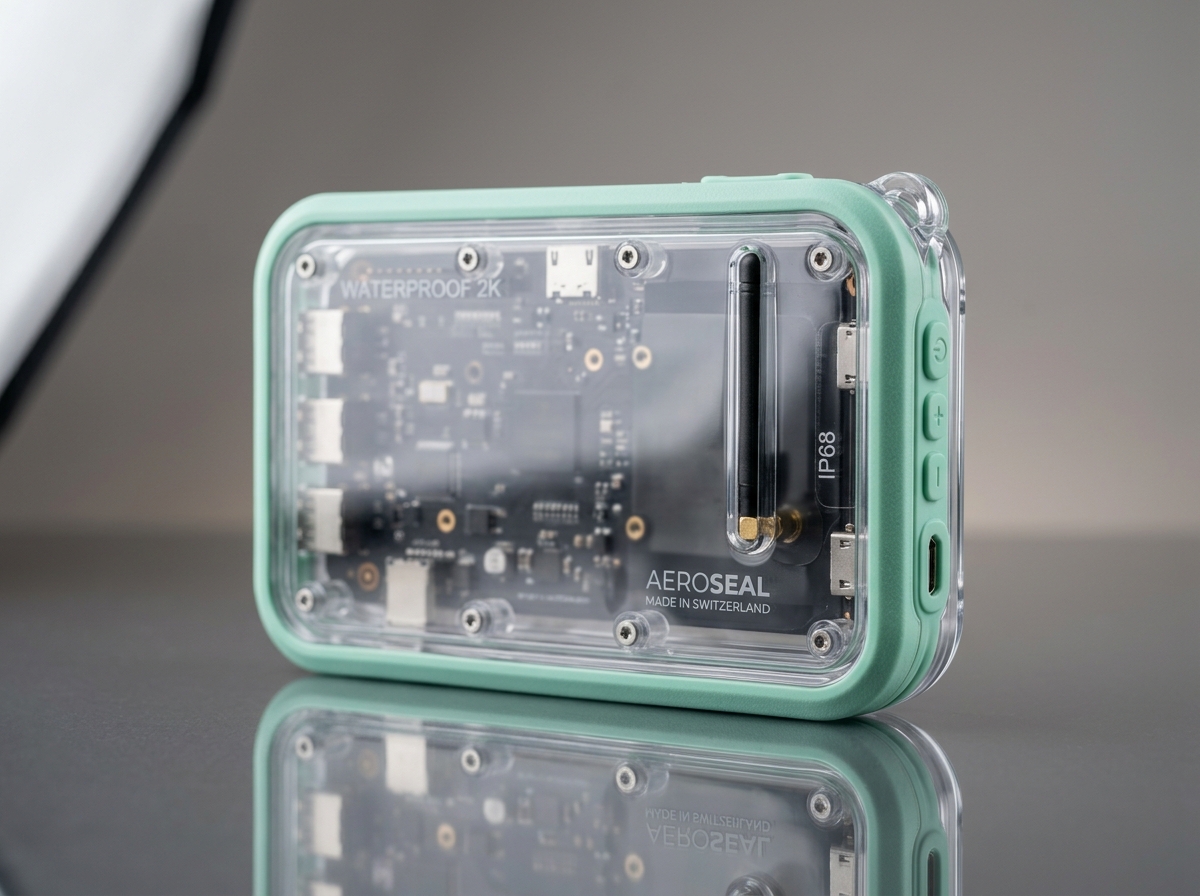
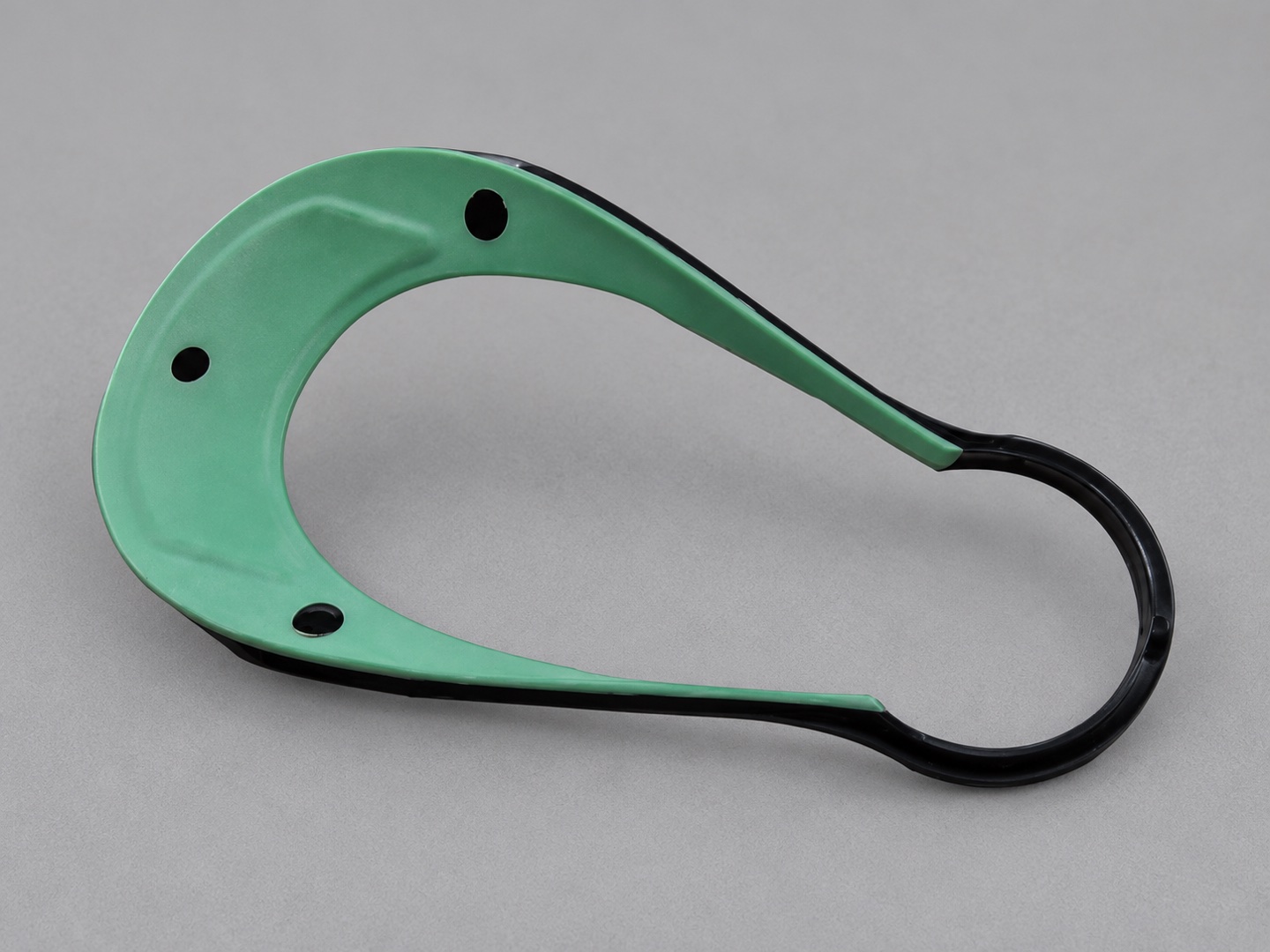
How Do Chemical Melt Fusion and Mechanical Interlocks Govern Overmolding Bond Strength?
Overmolding bond strength is governed by two complementary physical mechanisms: interfacial macromolecular interdiffusion (chemical melt fusion) and macroscopic geometric undercuts (mechanical interlocking). For durable industrial and electronic enclosures, achieving a cohesive peel strength above 35 N/cm requires matching the Hansen solubility parameters of the substrate and overmold while raising the interfacial contact temperature above the substrate glass transition or softening point.
When molten elastomer is injected over a solid thermoplastic substrate, genuine chemical adhesion occurs only if two thermodynamic conditions are met simultaneously: the two polymers must be miscible at the molecular boundary, and the incoming melt must transfer enough thermal energy to remelt a microscopic surface layer (typically 10 to 35 µm deep) of the rigid substrate before freezing.
- T_interface = Instantaneous boundary contact temperature upon elastomer impingement (°C)
- b_m, b_s = Thermal effusivity of overmold melt and solid substrate, where
b = √(k · ρ · C_p)(J / m²·K·s½) - T_melt = Overmold elastomer melt temperature at the gate (typically 200°C to 240°C for TPU/TPE)
- T_sub = Pre-molded rigid substrate surface temperature prior to second shot (60°C to 90°C in 2K rotary molding; 25°C to 50°C in transfer molding)
- P_peel = F_peel / w_strip = 90-degree peel resistance per unit width under ASTM D903 / VDI 2019 (Target: ≥ 25 N/cm for grips; ≥ 40 N/cm for IP67 seals)
Use the engineering compatibility matrix below during early part DFM review to select compatible rigid substrates and soft overmold elastomers:
| Rigid Substrate | Surface Polarity | Optimal Overmold Resin | Chemical Bond Rating | ASTM D903 Peel Strength | Mandatory Engineering Strategy |
|---|---|---|---|---|---|
| ABS & PC/ABS | High (Polar) | TPU, Copolyester TPE-E, Modified SEBS | Excellent (Cohesive) | 38 to 52 N/cm | Direct melt fusion at 210–230°C; keep substrate dry (< 0.02% moisture) |
| Polycarbonate (PC) | High (Polar) | TPU (Shore 60A–95A), Specialty TPE-S | Very Good | 32 to 45 N/cm | Warm mold cavity (60–80°C) prevents premature skin freeze and stress crazing |
| PA6 / PA66 (incl. 30% GF) | Moderate (Hygroscopic) | Polyamide-modified TPE, TPU, LSR (self-adhesive) | Moderate (Moisture sensitive) | 22 to 36 N/cm | Overmold within 4 hours of substrate molding or re-dry PA66 at 85°C for 4 hrs; add mechanical anchors |
| Polypropylene (PP) | Non-Polar (Low surface energy) | TPV (Santoprene), Polyolefin TPE-O, SEBS | Excellent with Olefin TPE | 35 to 48 N/cm | Olefinic interdiffusion forms true weld; incompatible with polar TPU without mechanical locks |
| PBT / PET (Glass-Filled) | Moderate-Low (Crystalline) | TPE-E (Hytrel), Specialty Adhesion TPE | Fair to Moderate | 18 to 28 N/cm | Combine high melt temperature (235°C) with through-hole rivets and perimeter retention grooves |
| Acetal (POM) | Very Low (Self-lubricating) | Any TPE / TPU / Silicone | None (Purely Mechanical) | < 5 N/cm (Adhesive fail) | Chemical bonding is ineffective; 100% reliant on macroscopic undercuts, through-cores, and wrap-around geometry |
What Are the Critical DFM Rules for Overmold Wall Thickness, Shut-Off Lands, and Mechanical Undercuts?
The critical DFM rules for plastic overmolding require maintaining a uniform elastomer wall thickness of 1.0 to 2.5 mm, designing a 0.5 to 0.8 mm vertical step shoulder at every material boundary to eliminate peeling feather edges, and machining a 0.03 to 0.05 mm compression interference land on the rigid substrate where the second-shot steel cavity seals off.
Because thermoplastic elastomers (TPE/TPU) and liquid silicone rubbers (LSR) exhibit strong shear-thinning behavior under injection pressure, molten elastomer easily penetrates gaps narrower than 0.015 to 0.020 mm. If the rigid substrate shrinks unevenly or lacks a dedicated compression shut-off land, unsightly elastomer flash will bleed across cosmetic surfaces.
| Geometric Feature | Recommended DFM Specification | Failure Mode if Violated | Tooling & Process Countermeasure |
|---|---|---|---|
| Elastomer Layer Thickness | 1.0 to 2.5 mm (Max 3.5 mm locally) | Flow hesitation, air traps (< 0.8 mm); sink marks & long cycle (> 3.5 mm) | Core out thick grip pads with internal ribs; maintain substrate wall ≥ overmold wall |
| Boundary Transition Step | 0.5 to 0.8 mm perpendicular recessed ledge | Sharp "feather edge" (< 0.2 mm) curls and peels during handling | Meet cavity steel at a 90° shoulder so the TPE edge terminates in a full 0.6 mm butt joint |
| Shut-Off Compression Interference | 0.03 to 0.05 mm crush rib or sealing land (1.5 mm wide) | Elastomer flash bleeding onto rigid cosmetic housing | Size overmold cavity 0.04 mm tighter than nominal substrate OD at the sealing perimeter |
| Shut-Off Draft Angle | 3° to 5° minimum on sliding/kissing shut-offs | Substrate scuffing, shaving, or core galling during mold clamping | Use hardened S136 or H13 inserts with precision slow wire-cut EDM shut-offs |
| Through-Hole Mechanical Rivets | Hole Ø 2.5 to 4.0 mm with 0.8 mm counterbore flange | Delamination when exposed to oils, sweat, or thermal shock | Allow elastomer to flow through substrate apertures andmushroom on the reverse side |
During the overmolding shot, cavity melt pressure reaches 30 to 60 MPa against the pre-molded plastic substrate. If the rigid substrate is hollow or unsupported underneath the gating zone, the hot elastomer will deflect or crush the substrate wall. Always locate internal support ribs directly beneath the overmold gate and ensure the second-shot core pin fully backs up the internal face of the substrate.
Send us your 3D CAD assembly (.STEP / .IGES). Our Shenzhen tooling engineers will evaluate your substrate-to-elastomer shut-offs, mechanical interlocks, and metal insert boss ratios within 24 hours.
How Do You Prevent Boss Hoop Stress Cracking and Resin Flash in Metal Insert Molding?
Preventing boss cracking and thread flash in metal insert molding requires sizing the outer plastic boss diameter to at least 2.0 to 2.5 times the metal insert outer diameter (D_boss ≥ 2.0 × D_insert), pre-heating metal inserts to 100°C to 120°C prior to molding, and utilizing precision ground core pins (±0.005 mm clearance) that seal against a flush unknurled shoulder on the insert.
The primary mechanical failure mode in insert molding is circumferential tensile hoop stress (σ_θ). Metals such as C36000 brass (α_m ≈ 19 × 10⁻⁶ K⁻¹) and SUS304 stainless steel (α_m ≈ 17 × 10⁻⁶ K⁻¹) contract minimally upon cooling, whereas surrounding thermoplastics (α_p ≈ 55 to 85 × 10⁻⁶ K⁻¹) shrink 0.5% to 1.8% toward the rigid metal core. If the plastic wall around the insert is too thin or contains a sharp hex corner teamed with a cold weld line, radial stress cracks will propagate either immediately after ejection or within days of storage.
- σ_θ(r_i) = Maximum circumferential tensile hoop stress at the inner plastic-to-metal interface (MPa) (Must remain < 50% of polymer tensile yield strength)
- E_p, ν_p = Secant relaxation modulus (MPa) and Poisson's ratio of the molded polymer
- Δα · ΔT = Differential thermal strain
(α_p - α_m) · (T_softening - T_ambient) - r_i / r_o = Ratio of metal insert outer radius (r_i) to plastic boss outer radius (r_o). As r_o / r_i ≥ 2.2, hoop stress drops into the safe elastic design envelope!
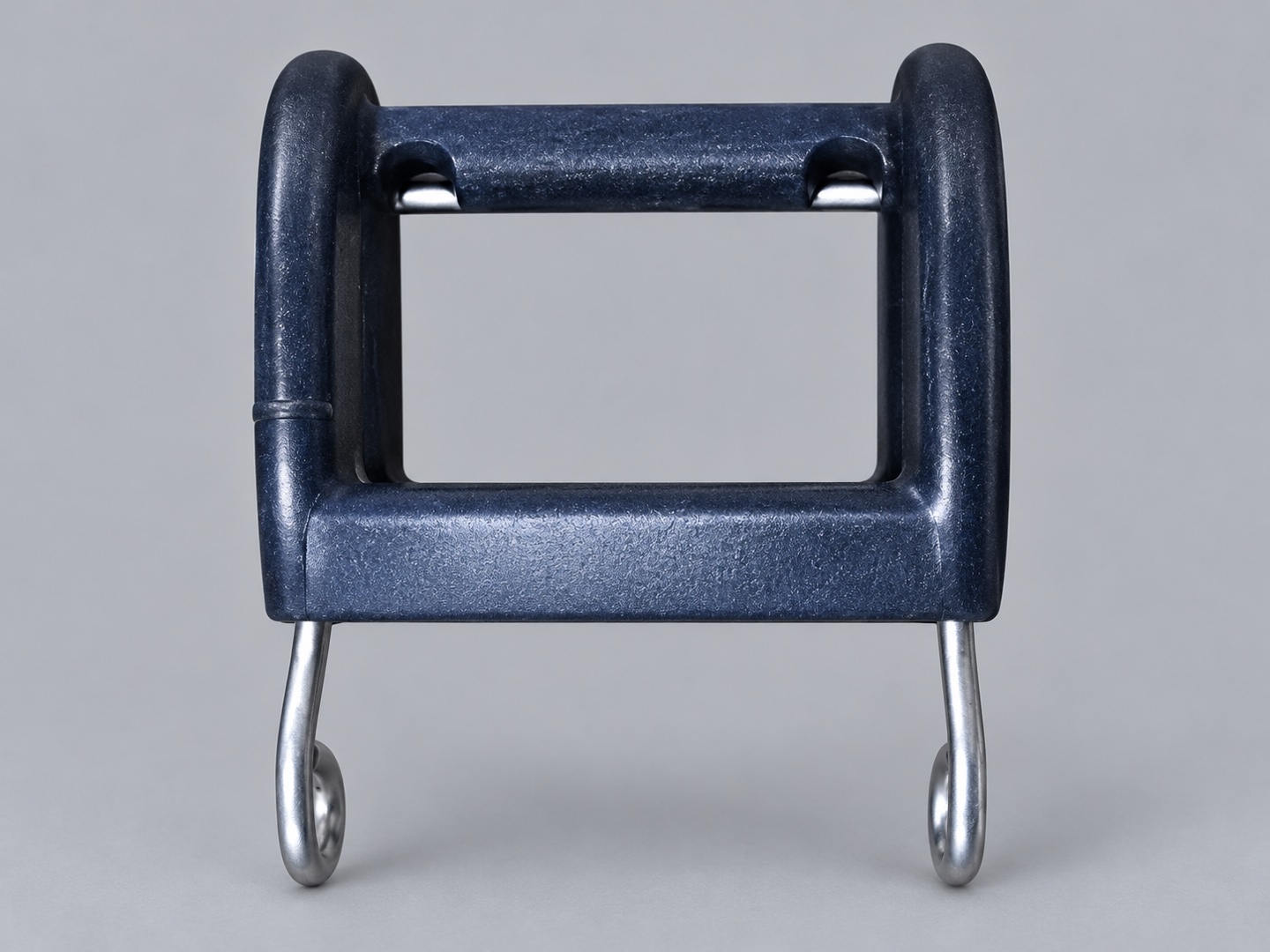
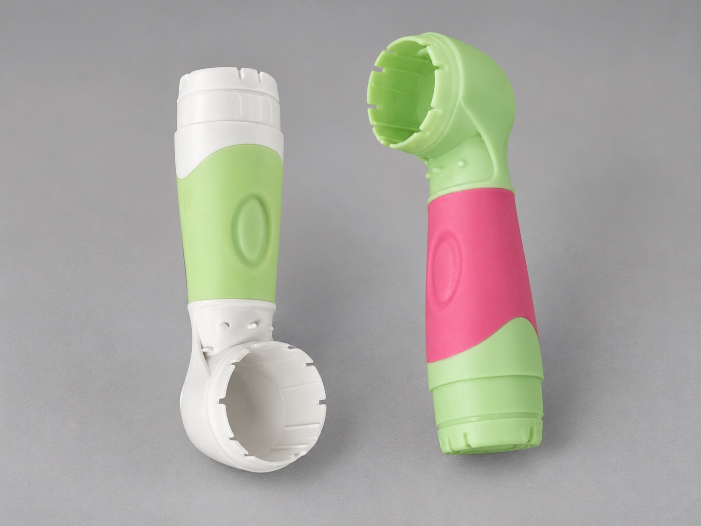
Follow these quantitative design parameters for threaded bushings, dowel pins, and stamped electrical terminals:
| Insert Alloy & Type | Min. Boss OD Ratio (D_boss / D_insert) | Knurl & Undercut Geometry | Pre-Heating Target | Typical Axial Pull-Out & Torque Resistance |
|---|---|---|---|---|
| C36000 Brass Threaded Bushing (M3–M6) | 2.0x (Glass-filled) / 2.3x (Unfilled PC, ABS) | 45° diamond knurl (pitch 0.8 mm) + 2 radial undercut grooves; 0.6 mm unknurled pilot guide | 90°C to 110°C | 1,400 to 3,800 N pull-out; 4.0 to 10.5 N·m torque |
| SUS 303 / 304 Stainless Dowel & Studs | 2.2x to 2.5x | Annular retention collars with R0.3 mm filleted root radii (avoid sharp 90° stress risers) | 110°C to 130°C | 2,200 to 5,200 N pull-out; high shear load capacity |
| C11000 / C5191 Stamped Copper Busbars & Pins | Min. 1.2 to 1.5 mm encapsulation wall per side | Stamped through-apertures (Ø 1.5–2.5 mm) for plastic cross-bridging + micro-surface roughening | 80°C to 100°C | Hermetic tracking resistance; passes 1,500V HiPot dielectric test |
| 6061 / 7075 Anodized Aluminum Chassis Inserts | 1.8x to 2.0x (Closer CTE match to plastic) | CNC-machined perimeter dovetail pockets + bead-blasted or laser-textured bonding face | 90°C to 110°C | Structural load distribution across hybrid metal-plastic frames |
Never extend diamond knurling all the way to the flush mating face of a threaded insert! If the knurl touches the mold cavity wall, molten plastic will jet through the knurl valleys and flood the internal screw threads. Always specify a smooth, unknurled cylindrical pilot shoulder at least 0.6 to 1.0 mm long (held to ±0.02 mm OD tolerance) at the open end of the insert so the mold cavity steel can seal cleanly around the outer perimeter.
When Should You Choose Two-Shot (2K) Rotary Molding vs. Pick-and-Place Transfer Overmolding?
Choose two-shot (2K) rotary injection molding when annual production volume exceeds 35,000 to 50,000 parts and maximum chemical peel adhesion is required, as the second shot is injected immediately while the substrate is still at 70°C to 90°C. Choose pick-and-place transfer overmolding (two separate molds in standard presses) for volumes under 35,000 units/year, rapid bridge production, or assemblies integrating metal inserts and electronic sub-components.
| Comparison Parameter | Two-Shot (2K) Rotary / Core-Back Molding | Pick-and-Place Transfer Overmolding |
|---|---|---|
| Tooling Investment | Higher (1.6× to 2.2× single mold cost; requires complex rotary platen or core-back kinematics) | Lower (1.0× substrate mold + 0.8× overmold tool; runs on standard Haitian 80T–400T presses) |
| Piece-Part Cycle Cost | Lowest (Single 25–45s machine cycle; zero manual handling labor) | Moderate (Two press cycles; vertical press operator or robotic EOAT loading) |
| Chemical Bond Integrity | Maximum (Substrate remains hot and uncontaminated inside the closed press environment) | High (Requires clean handling, controlled storage time, and higher overmold melt temperatures) |
| Dimensional Repeatability | Ultra-high (DIN 16742 TG3/TG4; substrate stays locked on the same core throughout both shots) | Good (TG4/TG5; requires account for post-mold shrinkage of substrate before loading into second tool) |
| Optimal Annual Volume | > 35,000 to 500,000+ parts / year | 500 to 35,000 parts / year (Ideal for industrial instruments & multi-insert housings) |
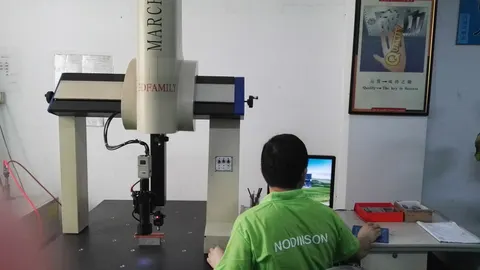
In pick-and-place transfer overmolding, the rigid substrate cools to room temperature (20°C) for 24+ hours before being loaded into the overmolding tool. By that time, the substrate has already completed 85% to 95% of its volumetric mold shrinkage. The overmolding tool core and shut-off lands must be machined to match the actual shrunk substrate dimensions (verified via 3D CMM FAI measurement after T1 substrate sampling), rather than applying double shrinkage to both tools.
Frequently Asked Questions on Overmolding & Insert Molding Design
Why is my TPE overmold peeling off a glass-filled nylon (PA66-GF30) housing?
PA66-GF30 is highly hygroscopic and features 30% exposed glass fibers at the surface that reduce available polymer bonding area. If the nylon substrate absorbs ambient moisture above 0.15% before overmolding, steam micro-bubbles form at the interface and destroy chemical adhesion. Always dry PA66 substrates at 85°C prior to transfer overmolding, use a polyamide-grafted TPE or TPU grade, and incorporate mechanical through-hole interlocks.
What is the minimum plastic wall thickness required around a brass threaded insert?
For unfilled amorphous resins like PC, ABS, or PC/ABS, the plastic boss outer diameter should be at least 2.2 to 2.5 times the insert outer diameter (for example, a 5.0 mm OD M3 insert requires an 11.0 to 12.5 mm boss OD, or 3.0 to 3.75 mm wall thickness per side). For glass-reinforced resins like PA66-GF30 or PBT-GF30 with higher tensile strength and lower thermal shrinkage, a 1.8 to 2.0x boss diameter ratio is sufficient.
How do you prevent sink marks on the opposite side of a thick soft-touch overmold grip?
Just like standard single-material injection molding, thick elastomer sections accumulate thermal mass and shrink volumetrically toward the core. Keep the overmold layer between 1.0 and 2.5 mm uniform thickness by coring out raised contour features on the underlying rigid substrate rather than filling deep pockets purely with solid TPE.
Should I use mold-in brass inserts or ultrasonic heat-staked inserts?
Mold-in inserts provide 25% to 40% higher axial pull-out and rotational torque strength because molten resin flows under high injection pressure completely into the deep undercuts and knurls. Mold-in inserts are essential for high-load industrial fittings, blind-hole sealed housings, and vibration-critical electronics, whereas ultrasonic heat-staking is often chosen for simple consumer enclosures to simplify mold cycle automation.
Authoritative Standards & Engineering References
- ASTM D903 Standard: Standard Test Method for Peel or Stripping Strength of Adhesive Bonds (90-Degree Overmold Peel Qualification).
- VDI 2019 Guideline: Testing the Adhesion of Thermoplastic Elastomers (TPE) on Substrates (Verein Deutscher Ingenieure).
- ISO 20457:2018 / DIN 16742: Plastics Moulded Parts — Tolerances and Acceptance Conditions for Multi-Component and Insert Tooling.
- Plastics Industry Association (SPI): Engineering Guidelines for Insert Molding and Multi-Shot Tooling Classifications.